Table of Contents
Advertisement
Quick Links
Advertisement
Table of Contents

Related Manuals for PM BRIDGE6

Summary of Contents for PM BRIDGE6
- Page 1 THINK LESS. CREATE MORE. BRIDGE6 MIDI CONTROLLER USER MANUAL (V1.3.1)
- Page 2 This device was created and designed to empower your creativity. It is the result of many long nights and early mornings. It is born from the desire to bridge the gap between musician and instrument, and we want to say a huge thank you for your support.
-
Page 3: Table Of Contents
TABLE OF CONTENTS BRIDGE6 Overview ....................5 Technical Information..................6 Hardware Layout....................7 Quick Start......................9 1. Device Interface....................13 Footswitches OLED Display RGB LEDs 2. Power & Navigation..................14 Powering Your BRIDGE6 Basic Navigation Opening the Menu 3. Overview Of Connectors ................17 4. Flexiports ......................19... - Page 4 TABLE OF CONTENTS (CONT.) Aux Switches Boot Messages & Boot Delay Device Link 8. Message Stacks....................41 9. MIDI Clock .......................47 10. LFO’s ......................50 11. Switch Out.....................55 12. Aux Switch In ....................56 13. Switch Groups ....................58 Accessing and Editing Switch Groups 14.
-
Page 5: Bridge6 Overview
BRIDGE6 OVERVIEW The BRIDGE6 is a 6-switch MIDI foot controller with RGB LEDs, an OLED screen, and a super tough aluminium enclosure. It’s made in New South Wales, Australia and was the result of a successful Kickstarter campaign in 2020. Now PIRATE MIDI builds and sells MIDI devices all over the world. -
Page 6: Technical Information
Imperial (19.4 oz.) DISPLAY POWER REQUIREMENT OLED (3.2”) 9v DC or USB (200mA) BOX CONTENTS 1x BRIDGE6 MIDI foot controller 1x USB cable 4x Self-adhesive Rubber Feet LINKS TO DOWNLOADS: https://learn.piratemidi.com It’s important that firmware updates are installed when they are available. Old firmware may not be supported by the web editor. -
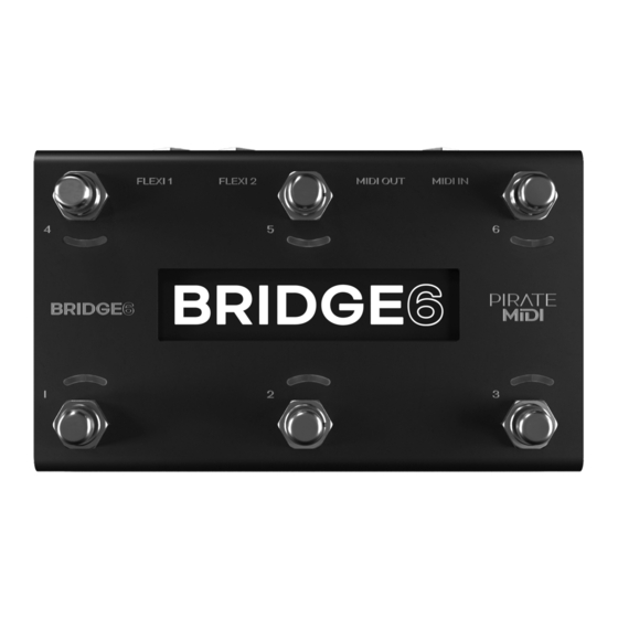
Page 7: Hardware Layout
HARDWARE LAYOUT 6 soft-touch footswitches. No clicking. Work with multiple press types (double-press, hold, etc). Heavy-duty aluminium enclosure with black anodising. Scratch-resistant and no flex. Bright, crisp, and easy to read OLED graphical display. Menus, icons, scribble strips are all a breeze on this beautiful display 12 RGB LEDs which you can assign to any colour you like for any function you like. - Page 8 HARDWARE LAYOUT (CONT.) USB type C (2m type A-to-C cable included) for USB MIDI, using the web editor, and powering the device. Dedicated ¼” (6.35mm) TRS MIDI In conforming to the MIDI.org specification. (i.e. Type A). Dedicated DIN5 MIDI Out conforming to the MIDI.org specification.
-
Page 9: Quick Start
QUICK START 1. Bank Up/Down To go to the next bank, press switch 2 and switch 3 together. To go to the previous bank, press switch 1 and switch 2 together. These can be customised or turned off (See chapter 18). 2. - Page 10 QUICK START (CONT.) 3. Don’t Miss the Rest! Many menus and settings have a second or third page of settings. Always make sure you haven’t missed vital settings by scrolling to the right using switch 6 until you get back to the first position. Move Left - FS4 Exit/Back - FS5 Move Right - FS6...
- Page 11 If you want to learn what these powerful settings are capable of, read more in chapter 13. Check that your BRIDGE6 firmware is up to date. Updates are released periodically adding new features and bug fixes. Go to: www.learn.piratemidi.com/downloads/firmware-updates ©...
- Page 12 Warning: technical documentation enclosed. Coffee required. © PIRATE MIDI 2023 - Firmware v1.3.1 www.learn.piratemidi.com...
-
Page 13: Device Interface
1. DEVICE INTERFACE Footswitches Six silent footswitches are the main interface on the BRIDGE6. Rated for over 100,000 presses each, they are able to send different MIDI message stacks for different press types (Toggle On, Toggle Off, Press, Release, Double Press, Hold, Hold Release etc). -
Page 14: Power & Navigation
2. POWER & NAVIGATION Powering Your BRIDGE6 You can power your BRIDGE6 with either a USB cable, or a centre-negative 9v DC jack (2.1mm) commonly used for guitar pedals. Centre-Negative DC Power USB Power Switching Power Sources The BRIDGE6 uses smart power switching so you can have both plugged in at once, and if you need to remove one or the other, the unit will seamlessly switch power sources without shutting down or restarting. -
Page 15: Opening The Menu
2. POWER & NAVIGATION (CONT.) There are 100 banks (0-99). Banking up from bank 99 will return you to bank 0. Banking down from bank 0 will send you to bank 99. Opening the Menu To enter the menu, press and hold down switches 1 & 4 simultaneously (as pictured below). - Page 16 2. POWER & NAVIGATION (CONT.) Press switch 1 or switch 3 to navigate the menu (note the arrows on screen). Press switch 4 or 6 to change bank or navigate horizontally in the menu (note the arrows on the screen. Press switch 2 to select or set (like an ‘enter’...
-
Page 17: Overview Of Connectors
From left to right: USB (type-C) The BRIDGE6 can be powered by USB, and is also a class-compliant USB MIDI device. This means it will be recognised as a MIDI device without any drivers. Use it with your DAW, plugins, or music apps. - Page 18 3. OVERVIEW OF CONNECTORS (CONT.) TRS Flexiports 1 & 2 ¼” (6.35mm) TRS jacks with 13 modes (and counting): • MIDI Out • Type A • Type B • Tip Active • Ring Active • Device Link • Exp-Doubler In •...
-
Page 19: Flexiports
Flexiport Modes Summary Each Flexiport on the BRIDGE6 is a 6.35mm (¼”) TRS Jack. They have 11 modes (and counting) that are assignable in the Menu under “Menu > Global > Flexiports > Flexiport ‘x’ > Mode”... - Page 20 4. FLEXIPORTS (CONT.) 9. Switch Out (Send TRS switch emulation to non-MIDI devices) 10. MS Relay (Send TRS commands to your Morningstar Omniport Relay Interface) 11. Strymon Fav Out (Emulates the Strymon Fav switch) 12. Tap Tempo Out (MIDI Clock as switch output) 13.
-
Page 21: Midi Out
4. FLEXIPORTS (CONT.) MIDI Out When set to ‘’MIDI Out’ mode, the Flexiport is a dedicated MIDI TRS Output. There are 4 MIDI Out modes: Type A, Type B, Tip Active, & Ring Active. You can choose the MIDI Out mode in the Global settings menu: Menu >... -
Page 22: Exp-Doubler In
4. FLEXIPORTS (CONT.) Expression Pedal Calibration Expression pedals will sometimes not register their full range on different devices they connect to. Calibrating your expression pedal will make sure that toe-down is equal to the maximum MIDI value (127) and heel-down is equal to the minimum value (0). -
Page 23: Tap Tempo Output
4. FLEXIPORTS (CONT.) An expression pedal usually works with three contacts: Tip, Ring, and Sleeve. The Ring supplies power, the Sleeve is connected to ground, and the Tip transmits the position of the pedal. Our Exp-Doubler supplies power to the Ring of your expression pedals which leaves an extra slot on the Flexiport for receiving the pedal position. -
Page 24: Switch Out
4. FLEXIPORTS (CONT.) Menu > Aux Switches > Aux Switch ‘x’ (For bank-level Aux messages) Using these menus you will now be able to assign messages for up to 3 auxiliary switches (Tip, Ring, Tip+Ring). The available messages are Press, Hold, Toggle On, and Toggle Off. -
Page 25: Strymon Fav Switch Out
4. FLEXIPORTS (CONT.) Assigning ‘Switch Out’ Actions to a Footswitch Once you have set the Flexiport mode, you can set any message on any press type as a Smart Message with “TRS Out” function. Then choose None, Tip, Ring, or Tip+Ring as the switch action that will be triggered by that Smart Message. - Page 26 4. FLEXIPORTS (CONT.) Setting the Main/Satellite Roles To choose which device will broadcast it’s bank name and act as the Main device, go to: Menu > Global > Device Link Device Link Settings In the above-mentioned menu, there are currently 4 options after the Main/ Satellite choice.
-
Page 27: Midi In/Out/Thru
MIDI In The dedicated MIDI In on the BRIDGE6 is a 6.35mm (¼”) TRS Jack. Like the MIDI Out, it is not able to be changed to another function. It is a permanent MIDI In. - Page 28 5. MIDI IN/OUT/THRU (CONT.) To set the MIDI Thru routing go to: Menu > Global > MIDI > Thru Routing > ‘TRS In’ or ‘USB In’ This menu allows you to choose which MIDI Outs (Flexi 1, Flexi 2, DIN5, USB) the MIDI messages received on the chosen input (USB or TRS In) will be sent For example, if you choose to turn on MIDI Thru routing from the USB In to the DIN5 out, any message received on the USB In will be sent to the DIN5...
-
Page 29: Usb Midi
A USB host device like the CME WIDI UHOST will be a great addition to your BRIDGE6. Plug it into your USB port and go wireless! It also means that as a USB host device, you can connect the WIDI UHOST to a WIDI Jack or similar and use the USB MIDI in/out as another general MIDI in/out to the device the WIDI Jack is plugged into. -
Page 30: Messages And Modes
7. MESSAGES AND MODES You can program all the functions of your BRIDGE6 with the onboard menus or the web editor. We’ve made both methods as straightforward as possible so you can quickly get up and running. Here’s an overview of what you can do when programming your BRIDGE6. -
Page 31: Primary Footswitch Modes
7. MESSAGES AND MODES (CONT.) • Switch On • Switch Off • Switch Toggle • Reset Sequential • Increment Sequential Step • Decrement Sequential Step • Set Step Sequential • Queue Next Sequential Step • Queue Sequential Step • Reset Scrolling •... - Page 32 7. MESSAGES AND MODES (CONT.) The Primary LED will be toggled between On and Off along with the switch state. In the Global settings, you can choose whether changing banks will preserve the toggle states of switches, or whether all switches’ states are reset when changing banks.
- Page 33 7. MESSAGES AND MODES (CONT.) be started and stopped when the Start and Stop action is triggered. Sequential This mode will activate each message in the “Sequential” message stack individually, one at a time, when you press the footswitch. You have the option of making the last few messages repeat in a loop or reversing the messages back to the first step.
- Page 34 7. MESSAGES AND MODES (CONT.) and recording new loops. All will simply cycle through the steps again after reaching the end of the “direction.” Sequential Linked This mode lets you link to another Sequential mode footswitch within the current bank, but change parameters such as the direction or the send mode.
- Page 35 7. MESSAGES AND MODES (CONT.) Step Size This option sets the increment/decrement size of the scrolling value. Value can be set from 1-32. If the value of the messages as-saved is 0 and the step size is 3, the next value sent after 0 will be 3. If the step size is 32, the values 0-127 will be covered in 4 presses.
- Page 36 7. MESSAGES AND MODES (CONT.) This behaviour allows for two different toggle message stacks to be accessed using a single footswitch (Primary and Secondary toggle) Hold time is adjustable in the Global Interface settings. Secondary Toggle stacks each have an 8-message limit. Double Tap Momentary This mode allows you to activate the Double Tap message stack with a double press of a footswitch.
-
Page 37: Expand & Improve Your Midi Routing
For example, a TC Electronics Plethora X5 has 5 knobs which are also controllable with MIDI CCs. By applying the LFO to one of those MIDI CCs, the BRIDGE6 can continually (and automatically) ‘move’ that knob. Many effects units have parameters that can be controlled in this way. Almost every parameter on multi-effects units like the Line6 Helix and Fractal Audio devices can do this. -
Page 38: Expression Pedals
7. MESSAGES AND MODES (CONT.) The BRIDGE6 LFOs can be set to activate with the Primary or Secondary switch function. This can product a “toggle” type or “momentary” type effect (i.e. press once to turn on, press again to turn off, OR press to activate, release to stop) The LFO will oscillate all possible MIDI messages that are in the chosen MIDI message stack. -
Page 39: Aux Switches
You can add up to 16 messages of any type that are sent as soon as your BRIDGE6 is turned on. This is useful for making sure your connected gear is set to a “default” or “beginning” state without having to check everything. -
Page 40: Device Link
Menu > Global > Interface > General UI > Boot delay You can increment the boot delay by 100ms from 0ms to 20000ms (20 seconds) to allow other gear to power on before the BRIDGE6 sends the Power-on messages. Device Link... -
Page 41: Message Stacks
8. MESSAGE STACKS MIDI Messages Onboard You can add MIDI messages for switch presses (per bank), expression pedals (per bank and global) but the method is essentially the same for each, you just find them in different places in the menu. 1. - Page 42 8. MESSAGE STACKS (CONT.) Pressing switch 6 will delete the message you’re currently viewing in the stack. You will be asked to confirm your choice. “Edit: ‘x’” If there are multiple messages in the stack, you can scroll through them using switches 1 &...
- Page 43 8. MESSAGE STACKS (CONT.) 2. Expression Pedals Viewing Messages on Expression Pedals To view bank-level expression pedal messages, go to: Menu > Exp Pedals > Exp ‘xx’ > Bank Messages All controls are the same as on switches. To view global expression pedal messages, go to: Menu >...
- Page 44 8. MESSAGE STACKS (CONT.) 1. Linear 2. Log © PIRATE MIDI 2023 - Firmware v1.3.1 www.learn.piratemidi.com...
- Page 45 8. MESSAGE STACKS (CONT.) 3. Reverse Log ANTI-LOG SWEEP MIDI VALUE PEDAL POSITION 4. Inverse Linear 5. Inverse Log 6. Inverse Reverse Log 3. Bank Messages Each bank has its own stack of 16 messages. These messages are automatically sent when that bank is selected. To access this message stack for viewing and editing, go to: Menu >...
- Page 46 Menu > Global > Aux Messages > Aux Switch ‘x’ 5. Boot Messages A stack of 16 messages can be set to be sent immediately after the BRIDGE6 is powered on. To set these messages, go to: Menu > Global > Boot Messages This is useful for making sure your connected gear is set to a “default”...
-
Page 47: Midi Clock
9. MIDI CLOCK MIDI Clock Onboard The BRIDGE6 has two onboard MIDI Clocks that can run simultaneously and independently with individual routing options. 1. Assigning MIDI Clock to a Footswitch To assign a MIDI clock to a switch, enter the menu and go to: Menu >... - Page 48 4. Sending MIDI Clock as Analog Tap Impulses Some devices like the BOSS DD-20 giga delay have an external tap input designed for a tap tempo external footswitch. The BRIDGE6 can send MIDI clock impulses as “Tap Tempo Out” to control the tap tempo of these non- MIDI devices.
- Page 49 9. MIDI CLOCK (CONT.) 6. Controlling Clock Tempo with MIDI You can set the tempo for Clock A and Clock B using external MIDI commands sent to the MIDI in or USB MIDI In of the BRIDGE controller. Clock tempos can be adjusted using CC 73 and CC 74 as NPRN-style pairs. (NRPN is a way to extend the range of values of a MIDI CC by using two CC’s together instead of just one).
-
Page 50: Lfo's
10. LFO’S Setting LFOs The BRIDGE6 has six LFOs per bank that can run simultaneously and independently with deep customisation and flexibility. LFOs are assigned to a particular message stack on a particular switch. When active, the Primary LED becomes an indicator of the LFO, showing both frequency and wave shape with the pulsing/fading of the LED itself. - Page 51 Only two LFOs can be assigned per bank. If there are already two switches in the current bank with the LFO state set to ‘on’ the BRIDGE6 will tell you that there are no more LFO slots available and will not turn on the LFO.
- Page 52 10. LFO’S (CONT.) or other constant modulation. Hold will run the LFO only while you hold down the footswitch. This is useful for one-off intentional parameter changes, or for on-the-fly virtual knob twisting (press and hold to slowly turn up the MIDI-controllable gain knob on your drive pedal) or for Ramping effects like opening up a cutoff filter.
- Page 53 10. LFO’S (CONT.) © PIRATE MIDI 2023 - Firmware v1.3.1 www.learn.piratemidi.com...
- Page 54 10. LFO’S (CONT.) 7. LFO Messages This settings allows you to choose the message stack that the LFO will modulate. Any compatible message in this stack will be what the LFO uses to create the oscillating MIDI data. For instance, if you choose the toggle on stack, then any messages in the toggle on stack are what the LFO will oscillate.
-
Page 55: Switch Out
11. SWITCH OUT Setting TRS Out PIRATE MIDI Flexiports can act as TRS switch outputs to control non-MIDI devices. Each footswitch can send a specific Tip, Ring or Tip+Ring message for each press type. The TRS Out settings are per bank. 1. -
Page 56: Aux Switch In
12. AUX SWITCH IN Setting Up Auxiliary Switches PIRATE MIDI Flexiports can act as TRS switch inputs to offload some simple functions to external controls. 1. Activating Aux Switch In mode To enable auxiliary switch functions, please set your chosen Flexiport to Aux Switch In mode. - Page 57 If you have problems with a particular aux switch, you can message us or email us to get advice. It is possible that some devices will not be wired in a way that works properly with the BRIDGE6. If messages are not set in the Toggle On or Toggle Off stacks, the switches and the corresponding Flexiport UI on the main screen will act in Momentary Mode.
-
Page 58: Switch Groups
13. SWITCH GROUPS Switch groups are used to activate, toggle, or deactivate switches by pressing other switches. These groups can be simple or very advanced. The default settings allow for simple exclusivity such as is needed to emulate a “snapshot” mode or where only one switch in the group should be able to be active at one time. - Page 59 13. SWITCH GROUPS (CONT.) Use switch 4 to add a group member. Use switch 6 to delete a group member, and use switch 2 to edit the settings for how a group member behaves within the group. Below you can see an example of a switch group with members: If there are no group members, you will see this screen.
- Page 60 13. SWITCH GROUPS (CONT.) respond according to the Response Type (see next section) when it receives the “On” or “Off” state of another switch in the group. Whether it receives the “On” or “Off” state depends on the Broadcast setting as described above.
-
Page 61: Interface - Led's
14. INTERFACE - LED’S Each switch on the BRIDGE6 has a pair of LEDs. The left LED is called the Primary LED and the right is called the Secondary LED. The LEDs are RGB (multi-color) and can be customised per bank in the onboard menus or the web editor. -
Page 62: Led Behaviour
14. INTERFACE - LED’S (CONT.) If you are changing a custom color slot that already has a saved color, the saved color will appear in the primary LED position for you to compare to the new color you are creating in that slot. LED Behaviour Primary LEDs This LED function is linked to the current mode of the footswitch. -
Page 63: External Led Control
14. INTERFACE - LED’S (CONT.) Secondary LEDs This LED function is linked to the current mode of the footswitch. In Toggle mode, the secondary LED will light momentarily when the footswitch is held down. This helps you identify when a hold message has been triggered successfully. -
Page 64: Interface - Bank Names
15. INTERFACE - BANK NAMES All 100 Banks on the BRIDGE6 can be named individually with up to 16 Characters. Upper case, lower case, numbers, and symbols are available. Changing the Bank Name First, select the bank you want to change the name on. Then go to: Menu >... -
Page 65: Interface - Ui Mode
16. INTERFACE - UI MODE The User Interface (UI) of the BRIDGE6 main screen defaults to the Standard UI but it can be changed to the Simple UI if preferred. How to change the UI To change the UI from Extended to Simple, go to: Menu >... - Page 66 16. INTERFACE - UI MODE (CONT.) Depending on the mode that has been selected for the Flexiports, you will be given different graphical representations and helpful information here. In MIDI Out mode, the box will show a letter (A, B, T, R) indicating what TRS MIDI type is being used.
-
Page 67: Interface - Switch Labels
17. INTERFACE - SWITCH LABELS Each switch can be given a different name in all 100 banks on the BRIDGE6. These labels can be up to 8 characters. Here’s how to change them. Changing & Customising Switch Labels Go to: Menu >... -
Page 68: Bank Navigation
Menu > Global > Interface > General UI Then, scroll to the second page to change the bank triggers as shown in the diagram below. The options for bank triggers on the BRIDGE6 are: • FS1 + FS2 • FS2 + FS3 •... -
Page 69: Copy/Paste & Templates
19. COPY/PASTE & TEMPLATES To make message and bank duplication easier and faster in the onboard menus, we’ve included the ability to create a new bank using a different bank as a starting template. You can also copy & paste individual switches, including all their settings and messages to another switch. -
Page 70: Copying Switches
19. COPY/PASTE & TEMPLATES (CONT.) Copying Switches With the “Copy From” feature, you can take the switch settings and messages from any other switch in any other bank, and paste it over your currently-selected switch. The first step is to go to the bank you where you want to paste the switch, then go to: Menu >... -
Page 71: Other Global Settings
If you want to make sure that messages coming into the BRIDGE are passed thru, and not interpreted as BRIDGE control messages, you’ll need to change the MIDI channel of the BRIDGE6 to a specific number (perhaps 16?) and then make sure your other messages are not using channel 16. -
Page 72: Program Change (Pc) Bank Output
20. OTHER GLOBAL SETTINGS (CONT.) Program Change (PC) Bank Output By default, your BRIDGE6 will automatically send a Program Change (PC) MIDI message when you change banks. This is really useful for plugging into another device like a HX Stomp and having the presets stay in sync with the banks. -
Page 73: Resetting Or Updating
Up to date information for firmware updates can be found at www.learn. piratemidi.com/downloads/firmware-updates The BRIDGE6 can be updated through the firmware updater app, or using a manual firmware update method as a last resort. Both are outlined in the webpage linked above. -
Page 74: Troubleshooting
In case of some kind of software error where you are unable to use the onboard menus, you can enter the firmware update mode manually: • Turn off the BRIDGE6 • Connect a TS or TRS ¼” cable between the two Flexiports. -
Page 75: Midi Implementation
22. MIDI IMPLEMENTATION The BRIDGE6 can itself be controlled by MIDI from an external MIDI device via the dedicated MIDI In (6.35mm TRS) or USB MIDI. You can set the MIDI channel in the menu (see Global Settings for more details): Menu >... - Page 76 22. MIDI IMPLEMENTATION (CONT.) FUNCTION MIDI CC# VALUE LED Control Override LED colours with external MIDI Off (0) 31-42 (FS1 Primary LED Control Toggle (64) - FS6 Secondary) On (127) 43-54 (FS1 Primary LED Brightness 0-127 - FS6 Secondary) 0-11 (FS1 Primary - LED Color Change Target FS6 Secondary) Red Channel Intensity...
-
Page 77: Support & Warranty
23. SUPPORT & WARRANTY Thank you for purchasing a BRIDGE6! If you have any questions, please feel free to contact us via support@piratemidi.com or use technical support at: www.learn.piratemidi.com Manufacturing defects are covered by our warranty. Please contact us if your device is defective.
Need help?
Do you have a question about the BRIDGE6 and is the answer not in the manual?
Questions and answers