Table of Contents
Advertisement
Quick Links
MODULAR UNIVERSAL ACTUATOR
Instruction Manual
North America, South America & Australia/Oceania
VICI Valco Instruments Co. Inc.
sales: 800-367-8424
tech:
713-548-2700
email: valco@vici.com
APPLICABLE MODELS
This manual is applicable to the following models:
•
UMH
•
UMD
•
UMT
Version 2 : 04-2023
Europe, Asia & Africa
VICI AG International
tel:
41 41 925-6200
fax:
41 41 925-6201
email: info@vici.ch
1
Version 2 : 04-2023
Advertisement
Table of Contents

Related Manuals for VICI UMH


Summary of Contents for VICI UMH
- Page 1 MODULAR UNIVERSAL ACTUATOR Instruction Manual North America, South America & Australia/Oceania Europe, Asia & Africa VICI Valco Instruments Co. Inc. VICI AG International sales: 800-367-8424 tel: 41 41 925-6200 fax: 41 41 925-6201 tech: 713-548-2700 email: info@vici.ch email: valco@vici.com Version 2 : 04-2023...
-
Page 2: Table Of Contents
MODULAR UNIVERSAL ACTUATOR Instruction Manual TABLE OF CONTENTS 1. Introduction ............................3 1.1. Description ............................3 1.2. Getting Started ...........................3 1.3. Multiposition Valve Switching Times ....................4 1.4. Two-Position Valve Switching Times ....................4 1.5. Modular Universal Actuator Components ...................6 2. Control Port Functions ......................... 7 2.1. -
Page 3: Introduction
Instruction Manual 1. INTRODUCTION 1.1. Description The VICI universal actuator models are designed to work with both two position and multiposition valves, with any number of ports. This is accomplished through simple programming via the manual remote or the serial port. -
Page 4: Multiposition Valve Switching Times
Actuator torque and speed are functions of the specific actuator assembly, which are designated as Models UMH, UMD and UMT, in order of increasing torque/ decreasing speed. All models have different gearboxes which provide differing speed and torque values. See the table below. - Page 5 MODULAR UNIVERSAL ACTUATOR Instruction Manual 1.4.1. Basic Operation with the Manual Remote The manual remote provides simple valve positioning capabilities, but in the setup mode, it can also be used to execute extensive actuator setup functions. For more information, refer to Setup Mode: Using the Manual Remote to Configure the Actuator.
-
Page 6: Modular Universal Actuator Components
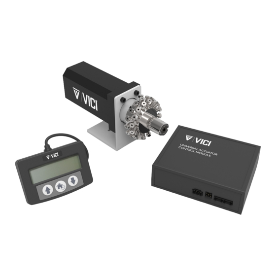
MODULAR UNIVERSAL ACTUATOR Instruction Manual 1.5. Modular Universal Actuator Components Version 2 : 04-2023... -
Page 7: Control Port Functions
MODULAR UNIVERSAL ACTUATOR Instruction Manual 2. CONTROL PORT FUNCTIONS Basic actuator control functionality facilitates position switching in two position mode, and STEP and HOME functions in the multiposition mode. This is done via direct input signals from switch closures, relay contacts, or TTL-compatible interfaces. - Page 8 MODULAR UNIVERSAL ACTUATOR Instruction Manual 2.1.1 Two position modes Digital Input Modes: Four input mode options are provided to expand the control flexibility of the actuator. The factory default setting is Mode 1. All four modes are described below. The mode is set via the serial port using the SMn command and is retained even when the power is cycled to the controller.
-
Page 9: Multiposition Modes
MODULAR UNIVERSAL ACTUATOR Instruction Manual 2.2. Multiposition modes 2.2.1. Step Command Applying a 25 mSec low signal to the “Step” input pin causes the actuator to move to the next position in the currently-set direction of rotation. 2.2.2. Home Command Applying a 25 mSec low signal to the “Home”... -
Page 10: Switching Serial Modes
Transmit to host A (–) Receive from host B (+) * These pin numbers are used in the VICI cable I-22697 PIN 1 PIN 1 3.2. Switching serial modes As discussed in the “Using the Device ID Feature” in Section 3.4, all RS-485 communications require an ID. If the actuator has had an ID set previously, that ID will be recalled and retained. -
Page 11: Establishing Serial Communication
MODULAR UNIVERSAL ACTUATOR Instruction Manual 3.3. Establishing Serial Communication Serial communications with the device can be established using terminal emulation software (such as PuTTY or CoolTerm) running on a PC or compatible computer. Set the serial port parameters to the factory default of 9600 baud, no parity, 8 data bits, 1 stop bit, no hardware or software handshaking. - Page 12 MODULAR UNIVERSAL ACTUATOR Instruction Manual MA<enter> 1, 2, 3 Displays the current motor setting MAaaa<enter> 1, 2, 3 Sets the controller to operate the type of motor assembly to be used: EMH, EMD or EMT NP<enter> 2, 3 Displays the number of positions the actuator is currently set to index NPnn<enter>...
-
Page 13: Using The Device Id Feature
MODULAR UNIVERSAL ACTUATOR Instruction Manual 3.5. Using the Device ID Feature When an ID is set, the actuator responds only to commands which begin with the correct ID prefix, and its serial transmit output is disabled when not sending data. This allows up to 10 actuators to be controlled from one computer serial port. - Page 14 MODULAR UNIVERSAL ACTUATOR Instruction Manual To set up the actuator in this mode: 1. With no valve on the actuator, type AM1<enter> to set the actuator to Mode 1, Two Position With Stops. 2. Install the valve on the actuator, ensuring the valve is flush on the clamp, and the clamp screw is tight. 3.
-
Page 15: Command Reference
MODULAR UNIVERSAL ACTUATOR Instruction Manual In this mode, a CW command moves the actuator in the “positive” or “up” direction, like position 4 to position 5, while CC moves the actuator in the “negative” or “down” direction, like position 5 to position 4. •... - Page 16 MODULAR UNIVERSAL ACTUATOR Instruction Manual CNT[nnnnn] Displays the current number of actuation cycles, or resets the counter to zero, where nnnnn = 0 to 2,147,483,647 Modes Available All: In two position modes (1 & 2), the counter is incremented every time the valve moves. In the multiposition mode (3), the counter is incremented by the number of positions the valve moves;...
- Page 17 MODULAR UNIVERSAL ACTUATOR Instruction Manual GO[nn] Tells the actuator to go to position nn, where nn = 1 to NP (multiposition, mode 3), = ‘A’ or ‘B’ (two position, modes 1 and 2) (see also NP and SM commands) Modes Available All (see below) Ex.
- Page 18 MODULAR UNIVERSAL ACTUATOR Instruction Manual Initialization procedure required for installation or reinstallation of two position valves with stops. This command teaches the actuator where the valve physical stops are located for both positions of the valve. When issued, the actuator immediately starts the learning process which involves several moves back and forth. Modes Available Mode 1 (Two position with stops).
- Page 19 MODULAR UNIVERSAL ACTUATOR Instruction Manual In Two Position Mode (AM1,2) SM(n) sets the function of the Control Port inputs from 1 to 4 as follows: SM 1 (dual signal control mode) SM 2 (single signal toggle mode) SM 3 (state mode with enable) SM 4 (state mode with disable) In Multiposition Mode (AM3), SM(n) sets the direction of rotation for the actuator, where a is: F: Forward (toward the next highest numeric position),...
-
Page 20: Optional Bcd Interface
MODULAR UNIVERSAL ACTUATOR Instruction Manual Toggles the actuator to the opposite position from its current position; i.e., if the actuator is currently in Position B, it will toggle to Position A. Modes Available Two position (1 and 2) Example Command: TO<enter>... -
Page 21: Digital Input Signal Definitions
MODULAR UNIVERSAL ACTUATOR Instruction Manual The inputs are held to a logical high (+5 volts) by pull-up resistors and are designed to be driven low either by contact closure, 5 volt digital logic, or open collector transistor outputs. The signal polarity is defined as “negative true”... -
Page 22: Digital Input Protocols
MODULAR UNIVERSAL ACTUATOR Instruction Manual 4.3. Digital Input Protocols The digital input mode can be configured by using the serial SD command (as shown above) or by using the Universal Manual Remote menu options Interface Setup > BCD (as shown below). BCD (Binary Coded Decimal) (SD0) (default) For the 96 possible input positions, all 8 digital input data lines are required. -
Page 23: Additional Digital Input & Output Signals
MODULAR UNIVERSAL ACTUATOR Instruction Manual Pin Signal Definitions for the Various Input Modes MODE DATA INPUT LINES Input Type Parallel Binary 1BCD 2BCD 4 BCD 10BCD 20BCD 40BCD 80BCD – – – – – – – – – – – –... - Page 24 MODULAR UNIVERSAL ACTUATOR Instruction Manual Step Input Holding this signal low for a minimum of 25 mSec causes the actuator to advance one position. Home Input (multiposition only) For the 96 possible input positions, all 8 digital input data lines are required. See the reference chart. Manual Direction Input (multiposition only) When the signal is high and a move is sensed, the actuator will move in a clockwise direction.
-
Page 25: Appendix A: Setup
MODULAR UNIVERSAL ACTUATOR Instruction Manual 5. APPENDIX A: SETUP 5.1. Setup Mode: Using the Manual Remote to Configure the Actuator In the absence of an optional RS-232, USB, or serial interface, the manual remote can be used to perform extensive actuator setup functions. 5.1.1 Accessing the Setup Mode To access the Setup mode, press and hold the HOME/SETUP button for 5 seconds. - Page 26 MODULAR UNIVERSAL ACTUATOR Instruction Manual 3. On the Multiposition Menu, press the HOME/SETUP button when Set positions is highlighted. 4. Use the UP and DOWN arrow buttons to move through the numbers until 10 is showing. Press the HOME/SETUP button. In the multiposition mode, “counterclockwise”...
-
Page 27: Appendix A: Menu Tree
MODULAR UNIVERSAL ACTUATOR Instruction Manual 6. APPENDIX A: MENU TREE Menu Tree Main Menu 1. Valve Setup 2. Interface Setup Press the Home Button 3. Information when the valve is ready With Stops? 1. Yes 2. No Set Ports: XX 1. -
Page 28: Appendix B: Mounting & Dimensions
MODULAR UNIVERSAL ACTUATOR Instruction Manual 7. APPENDIX B: MOUNTING & DIMENSIONS Version 2 : 04-2023... -
Page 29: Appendix C: Manual Remote Factory Mode
The Factory mode allows access to basic parameters which are set at the factory. These parameters should not be altered by the user except via direct consultation with a VICI Technical Support representative. Note: the new firmware version of the manual remote does not have access to these menus. -
Page 30: Appendix D: Serial Response Strings
MODULAR UNIVERSAL ACTUATOR Instruction Manual 9. APPENDIX D: SERIAL RESPONSE STRINGS 9.1. Modular Universal Command Response Reference Table, Setup = LG1,LG0” (factory default) TYPICAL ASCII HEXADECIMAL RESPONSE RESPONSES <NO RESPONSE> AM = 3* 0x41 0x4d 0x20 0x3d 0x20 0x33 0x0d <NO RESPONSE>... -
Page 31: Modular Universal Command Response Reference Table, = Lg0, Ifm0
MODULAR UNIVERSAL ACTUATOR Instruction Manual 9.2. Modular Universal Command Response Reference Table, Setup = LG0, IFM0 TYPICAL ASCII HEXADECIMAL RESPONSE RESPONSES 0x45 0x31 0x0d 0x41 0x4d 0x33 0x0d <NO RESPONSE> CNT10 0x43 0x4e 0x54 0x31 0x30 0x0d CP10 0x43 0x50 0x31 0x30 0x0d <NO RESPONSE>... -
Page 32: Modular Universal Command Response Reference Table, = Lg0, Ifm1
MODULAR UNIVERSAL ACTUATOR Instruction Manual 9.3. Modular Universal Command Response Reference Table, Setup = LG0, IFM1 TYPICAL ASCII HEXADECIMAL RESPONSE RESPONSES 0x45 0x31 0x0d AM3* 0x41 0x4d 0x33 0x0d CP10* 0x43 0x50 0x31 0x30 0x0d CNT10* 0x43 0x4e 0x54 0x31 0x30 0x0d CP10* 0x43 0x50 0x31 0x30 0x0d CP01*... -
Page 33: Modular Universal Command Response Reference Table, = Lg0, Ifm2
MODULAR UNIVERSAL ACTUATOR Instruction Manual 9.4. Modular Universal Command Response Reference Table, Setup = LG0, IFM2 TYPICAL ASCII HEXADECIMAL RESPONSE RESPONSES 0x45 0x31 0x0d 0x4d 0x31 0x0d 0x4d 0x31 0x0d 0x4d 0x30 0x0d AM3* 0x41 0x4d 0x33 0x0d 0x4d 0x31 0x0d 0x45 0x30 0x0d 0x4d 0x31 0x0d CP10... -
Page 34: Modular Universal Command Error Response Reference Table, Setup = Ifm0
MODULAR UNIVERSAL ACTUATOR Instruction Manual TYPICAL ASCII HEXADECIMAL RESPONSE RESPONSES LG0* 0x4c 0x47 0x30 0x0d MAEMH 0x4d 0x41 0x45 0x4d 0x48 0x0d NP10* 0x4e 0x50 0x31 0x30 0x0d SB9600* 0x53 0x42 0x39 0x36 0x30 0x30 0x0a 0x0d SD0* 0x53 0x44 0x30 0x0d SL0* 0x53 0x4c 0x30 0x0d 0x53 0x4d 0x41 0x0d... - Page 35 MODULAR UNIVERSAL ACTUATOR Instruction Manual ERROR TYPICAL ASCII HEXADECIMAL RESPONSE MODE CONDITION RESPONSES CW18 out of range E2 CW18 Invalid* 0x45 0x32 0x20 0x43 0x57 0x31 0x38 0x20 0x49 0x6e 0x76 0x61 0x6c 0x69 0x64 0x0d CW18 out of range CW18 = Bad command* 0x43 0x57 0x31 0x38 0x20 0x3d 0x20 0x42 0x61 0x64 0x20 0x63 0x6f 0x6d 0x6d 0x61 0x6e 0x64...
-
Page 36: Revision History
MODULAR UNIVERSAL ACTUATOR Instruction Manual 10. REVISION HISTORY DOCUMENT NAME DATE REASON FOR CHANGES VERSION [DD.MM.YYYY] VICI_MU Actuator_User Manual_V1.pdf 02.09.2022 New Manual Creation VICI_MU Actuator_User Manual_V2.pdf 04.25.2023 Updates to tables Version 2 : 04-2023...
Need help?
Do you have a question about the UMH and is the answer not in the manual?
Questions and answers