Table of Contents
Advertisement
Quick Links
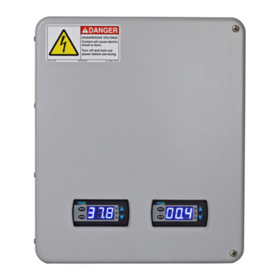
KE2 EvapPanel
Quick Start Guide
thermsolutions
Parts List
Kit #21958 KE2 Evap Panel (Single)
Kit #21959 KE2 Evap Panel (Double)
The following parts are included:
(1) KE2 Evap Panel1
A
(3) 40' colored temperature sensors1
B
(1) KE2 Terminal Board with fuses1
C
(2) ½" plastic knockout plugs1
D
(1) air sensor mount1
E
(4) wire ties (rated for low temp)1
F
(1) 2' Ethernet cable2
G
❶
21959 contains (2) KE2 Evap OEM controllers & displays, (6) 40' colored temperature sensors,
(2) KE2 Terminal Boards, (4) ½" plastic knockout plugs, (2) air sensor mounts, and (8) wire ties.
❷
Only in 21959.
Supplies
List
Basic accessories for the controller are included, however, certain truck
stock items are required to complete the installation.
Conduit to go between the controller and the evaporator (high &
V
low voltage).
Conduit connectors (straight or elbow as required).
V
High voltage wires matched to the load of the heaters, fans, liquid
V
line solenoid, and the controller (for ease of install consider using
the KE2 Wire Harness accessory).
Spade Connectors matched to the gauge of the high voltage wires.
V
Wire labeling (numbers, colors, etc.).
V
Controller Webpages
The controller has a built-in webpage for service. The webpage can
be accessed multiple ways, including: plugging the controller into
a KE2 Therm communication accessory like the KE2-Edge Manager
(KE2-EM), connecting the controller to a network/provide it
internet access, using the KE2 Service Tool App with an Ethernet
dongle, or by plugging a laptop directly into it.
Once on the webpage, logging in is required to make changes.
The defaults are: User Name: ke2admin Password: ke2admin
IMPORTANT: The password MUST be changed from the default
upon logging in for the first time for security purposes.
Installation Steps
Installation consists of mounting the panel, wiring the high voltage connections, wiring the low voltage connections (sensors, transducer & EEV if
used), and inputing the initial setpoints.
This reference should remain on site
with the installed KE2 Evap Panel.
A
B
E
G
F
Additional wire ties.
V
18 gauge twisted shielded pair, if extending sensor wires.
V
Foam insulation, if running wires outside the space.
V
Silicone (for sealing any box penetrations).
V
Popular Accessories
The following parts are available separately:
KE2 Wire Harness - 10' pn 20736, 25' pn 20670, 40' pn 20737
V
Door Switch - pn 20543
V
Further information on accessories can be found in the KE2 Condensed Catalog 411.
Additional Literature
Please visit:
https://ke2therm.com/literature/literature-ke2-evap-oem/
— OR —
use this QR code
Visit our YouTube channel for videos
on installation and setup.
Video 068 How to Determine Proper Coil Sensor
Location
Video 069 How to Properly Install a Coil Sensor
© Copyright 2023 KE2 Therm Solutions, Inc., Washington, Missouri 63090
Q.1.77 February 2023
NOTE:
All sensors can be used
for any purpose and
are interchangeable,
colors are for ease of
identi cation only.
C
D
youtube.com/ke2therm
Advertisement
Table of Contents

Subscribe to Our Youtube Channel
Summary of Contents for KE2 Therm Solutions EvapPanel
- Page 1 Video 069 How to Properly Install a Coil Sensor Installation Steps Installation consists of mounting the panel, wiring the high voltage connections, wiring the low voltage connections (sensors, transducer & EEV if used), and inputing the initial setpoints. © Copyright 2023 KE2 Therm Solutions, Inc., Washington, Missouri 63090...
- Page 2 2/3 down from top top of the evaporator, and 8 - 12 inches from 12” minimum coil in the return air of the evaporator. 8-12” 8-12” Return Air Blue (TAir) for Air Sensor © Copyright 2023 KE2 Therm Solutions, Inc., Washington, Missouri 63090...
- Page 3 Note: If a KE2-Edge Manager (KE2-EM) is on site, select DISABLED for NOTE: Custom valve setups are available via the webpage interface or KE2 Combo Display. KE2 SmartAccess. *Requires PN 21304 Solid State Relay N.O. © Copyright 2023 KE2 Therm Solutions, Inc., Washington, Missouri 63090...
- Page 4 Press and hold to save setpoint changes. ENTER Press to escape. BACK © Copyright 2023 KE2 Therm Solutions, Inc., Washington, Missouri 63090 KE2 Therm Solutions Q.1.77 February 2023 supersedes all prior publications. 12 Chamber Drive . Washington, MO 63090 1.888.337.3358 . www.ke2therm.com...
Need help?
Do you have a question about the EvapPanel and is the answer not in the manual?
Questions and answers