
Related Manuals for Witt MFA 9000


Summary of Contents for Witt MFA 9000
- Page 1 Instruction Manual for WITT-Analyser MFA 9000 Issue: 15.10.2015 This issue is not subject to change management Copyright WITT-GASETECHNIK GmbH & Co KG, 2015, all rights reserved...
-
Page 2: Table Of Contents
7.3.1 Set Offset Gas Concentration ....................20 7.3.2 Gain Gas Concentration ......................21 7.3.3 Offset Calibration ........................21 7.3.4 Gain Calibration ........................22 : +49 (0)2302 89010 WITT-GASETECHNIK GmbH & Co KG Salinger Feld 4-8 www.wittgas.com Gas Safety- & Control Equipment D-58454 Witten Fax: +49 (0)2302 89013 witt@wittgas.com... - Page 3 9.1 Sensor Specifications ........................45 9.1.1 Performance ........................... 45 9.1.2 Measuring gas / Carrier gas combinations and possible measuring ranges......45 9.1.3 Electrical (MFA 9000) ......................46 10 Attachment ......................... 46 : +49 (0)2302 89010 WITT-GASETECHNIK GmbH & Co KG Salinger Feld 4-8 www.wittgas.com...
-
Page 4: Notes On These Operating Instructions
Page 4 of 46 Notes on these operating instructions Thank you for having chosen a gas analyser from WITT-Gasetechnik! We are sure that you have made the right choice. With these operating instructions we would like to provide you with all information necessary for the safe intended use of the equipment and to provide instruction for safe, correct setting up and instal- lation, operation and checking of your analyser. -
Page 5: Rights To This Manual
As an appendix to these operating instructions you will find the technical data on the WITT gas analyser, the schemes given in the technical data, along with drawings and a list of symbols. -
Page 6: Safety Instructions And Precautionary Measures
All employees designated to handle the analyser shall be properly instructed and ad- vised of the applicable safety and health precautions. The WITT-analyser has been designed and built according to the state of the art. It shall only be used for its intended purpose. Any operation not conforming to the intended use or operation by inadequately trained personnel may result in hazardous operating conditions. -
Page 7: Measurement Of Burnable Gases
WITT-Service or when the instrument was used in a manner not conform- ing to its intended use, or if the operation did not follow the applicable national health and safety regulations. -
Page 8: Equipment Description
“Lance” on the rear for permanent analysing. For allowed inlet pressures see Technical Data. : +49 (0)2302 89010 WITT-GASETECHNIK GmbH & Co KG Salinger Feld 4-8 www.wittgas.com Gas Safety- & Control Equipment... -
Page 9: Technical Data Of The Analyser
Note! In order to supply sample gas to the analyser (e.g. from a WITT gas mixer or a gas mixture receiver) it is necessary to install a suitable gas line between the equipment where the gas sample is taken from and the corresponding analysis gas inlet port of the gas analyser. The installation of a suitable gas pipeline has to be performed by the customer. -
Page 10: Set Up And Installation
If the operating organisation is not in a position to perform a check, a check in accordance with DIN VDE 0702 can be performed by WITT Service. Warning ! In accordance with BGV A3 a protective earth connection (PE connection ) of protection class 1 must be provided. -
Page 11: Installation Of Gas Pipes
Any flow restrictions in the vent gas line shall be avoided. The supply of suitable calibration gases to the analyser is a customer responsibility. : +49 (0)2302 89010 WITT-GASETECHNIK GmbH & Co KG Salinger Feld 4-8 www.wittgas.com Gas Safety- & Control Equipment... -
Page 12: Electrical Installation
It is imperative that the supply voltage in the technical data is provided. Please note ! Do not yet switch on the power supply. : +49 (0)2302 89010 WITT-GASETECHNIK GmbH & Co KG Salinger Feld 4-8 www.wittgas.com Gas Safety- & Control Equipment D-58454 Witten Fax: +49 (0)2302 89013 witt@wittgas.com... -
Page 13: Commissioning And Operation
To switch on the gas analyser switch on the power supply. The warm up screen is shown in the display of the sensor / evaluator unit of the MFA 9000. Allow the analyser to warm-up. The shown count down must be expired. -
Page 14: Calibration Check / Calibration Of The Selected Gas Combination
Page 14 of 46 Calibration check / Calibration of the selected gas combination Note! You can find a more detailed description of operating the MFA 9000 when calibrating in Sec- tions 7.3.1 – 7.3.4. Note! Often a sufficient accuracy is achieved by a single point “Offset calibration”. -
Page 15: Shut-Down
Check adjustment of gas alarm respective gas is exceeded mixer • Check gas supply • Check threshold limit : +49 (0)2302 89010 WITT-GASETECHNIK GmbH & Co KG Salinger Feld 4-8 www.wittgas.com Gas Safety- & Control Equipment D-58454 Witten Fax: +49 (0)2302 89013 witt@wittgas.com... - Page 16 The gas analyser may only be returned into operation after it has been checked and repaired by us or an authorised service centre. : +49 (0)2302 89010 WITT-GASETECHNIK GmbH & Co KG Salinger Feld 4-8 www.wittgas.com Gas Safety- & Control Equipment...
-
Page 17: Operation Of The Analyser Module
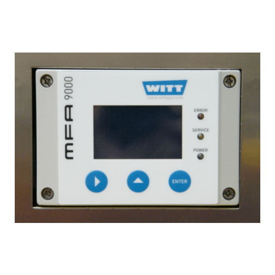
7.1.4 Operation Indicator (green) When this indicator flashes, it indicates that power is supplied and the internal processor works properly. : +49 (0)2302 89010 WITT-GASETECHNIK GmbH & Co KG Salinger Feld 4-8 www.wittgas.com Gas Safety- & Control Equipment D-58454 Witten Fax: +49 (0)2302 89013 witt@wittgas.com... -
Page 18: Right / Selection Key
“111.000” The MGM provides a list of up to 16 binary gas mixtures to be measured sequentially. It is described separately at the points where it is of interest. : +49 (0)2302 89010 WITT-GASETECHNIK GmbH & Co KG Salinger Feld 4-8 www.wittgas.com Gas Safety- &... -
Page 19: Warm Up Screen
0.30 H2/N2 After switching on and warming up the MFA 9000 shows the operation screen. Mainly it provides the user with the measured gas concentration. The first line gives the user status information. E.g. in occurrence of process alarms or a system error an appropriate indicator is shown. -
Page 20: Top Level Main Menu
Within this menu the operator can select where to go from here. If the item “Opera- tion” is selected (as shown) the MFA 9000 will return to the Operation screen by pressing <EN- TER> or <UP>. To get access to a submenu, first select the appropriate item and press <ENTER>. -
Page 21: Gain Gas Concentration
The current loop is refreshed. If the operator uses the option “YES” in the “Gain Calibration?” menu this starts the gain calibration procedure. : +49 (0)2302 89010 WITT-GASETECHNIK GmbH & Co KG Salinger Feld 4-8 www.wittgas.com Gas Safety- & Control Equipment... -
Page 22: Gain Calibration
------------ P001 The entire accessible individual configuration of the MFA 9000 is stored in about 200 Parameters. In the Parameter menu all configuration and actual measuring can be retrieved from the instru- ment. This may help to diagnose malfunction and mal settings. -
Page 23: Errors
Reset All? NO/YES The MFA 9000 continuously checks the internal electronic parts as well as the connected sensor against plausible values. If one or more of the actual states fit to the predefined alarm mask a sys- tem alarm is triggered and an error occurs. This is indicated in the first Display line by “Er”. In this case the system alarm indicator is flashing. -
Page 24: Setup
The Expert Setup enables access to all parameters, reset functions, access modes and codes and test signals for subsequent connected equipment. : +49 (0)2302 89010 WITT-GASETECHNIK GmbH & Co KG Salinger Feld 4-8 www.wittgas.com Gas Safety- & Control Equipment... -
Page 25: The Instrument Setup Menu
Internal calculation is always done on ppm level. Access of measuring values via the RS232 interface will always give the numbers in ppm with 1 ppm resolution. : +49 (0)2302 89010 WITT-GASETECHNIK GmbH & Co KG Salinger Feld 4-8 www.wittgas.com Gas Safety- &... -
Page 26: Measuring Gas Setup
In the second line the binary gas to be measured may be altered. The stored underlying list of dif- ferent measuring and carrier gases depends on the ordered configuration of the MFA 9000 and may contain up to 16 binary gas mixtures. -
Page 27: Response Time Setup
In the third line the temporal response of the instrument can be adjusted. The MFA 9000 has a build in exponential smoothing filter, with an adjustable T90 response time. It can be used to reduce fast variations in the reading due to fluctuation in the gas concentrations within the process as well as for reducing noise. -
Page 28: Multi Gas Mode List
“Is in list”. The stored underlying list of different measuring and carrier gases depends on the ordered configuration of the MFA 9000 and may con- tain up to 16 binary gas mixtures. -
Page 29: Relay 1 Mode
To select the R1 Mode submenu mark the first line by pressing <RIGHT> twice and then press <ENTER>. Depending on the MFA 9000 are a very versatile process interface. In order to setup this interface regarding the requirements the mode different submenus will appear on the display in line two and three. -
Page 30: Relay 1 Hysteresis
Not Failsafe means that the relay is normally open and closes when an error appears. Pressing <ENTER> the configuration will alternate between Failsafe and Not Failsafe. : +49 (0)2302 89010 WITT-GASETECHNIK GmbH & Co KG Salinger Feld 4-8 www.wittgas.com Gas Safety- & Control Equipment... -
Page 31: Relay 1 Active/Frozen During Calibration
All other settings for Relay 2 must be done in the same way like the settings for Relay 1 described in chapter 7.5.2.1 to 7.5.2.5. : +49 (0)2302 89010 WITT-GASETECHNIK GmbH & Co KG Salinger Feld 4-8 www.wittgas.com Gas Safety- & Control Equipment... -
Page 32: Common Relay
ESC/OK ESC/OK In the default setting the Common Relay indicates the internal state of the MFA 9000 only. Then the Alarm matrix contains all of the errors listed here: “EEPROM ERROR”, “CAL GAIN ER”, “CAL OFFS ER”,” CAL DEV ER”, “CAL VAR ER”, “BT MIN ER”, “BT MAX ER”, “BU MIN ER”, “BU MAX ER”, “TC MIN ER”, “TC MAX ER”, “EXTERNAL ER”. -
Page 33: Analog Output Setup
Analog Out 2 Adjust Loop The MFA 9000 is equipped with three analog outputs. The most important one is the isolated cur- rent loop. Two non isolated 0 to 10V outputs are also available for auxiliary quantities. 7.5.3.1 Current Loop Const. - Page 34 If you do not want to use the current output, set to 0.0 mA. : +49 (0)2302 89010 WITT-GASETECHNIK GmbH & Co KG Salinger Feld 4-8 www.wittgas.com Gas Safety- &...
-
Page 35: Analog Output 1
AOut1– Offset and AOut–Gain allows to scale the analog output according to a linear equation (Output = AOut1–Gain * signal + AOut1–Offset). : +49 (0)2302 89010 WITT-GASETECHNIK GmbH & Co KG Salinger Feld 4-8 www.wittgas.com Gas Safety- & Control Equipment... -
Page 36: Analog Output 2
19.500 mA. Entering the menu the MFA 9000 sets the loop current to 19.500 mA. Take a calibrator or a milli- meter to measure the actual loop current. To recalibrate the current loop of the MFA 9000 just type in the actual measured current. -
Page 37: Expert Setup
Within the expert level the user has the possibility to set or change all parameters as well as reset the MFA 9000 to its default parameters. Also within the expert level it is possible to change the codes to access the operator and the expert level. Furthermore the subsequent equipment can be tested for correct settings and connection by simulating alarm states and feed analog outputs. -
Page 38: Access Modes
The Operation Mode “3.00000” is a safe mode. Each alteration in this mode requires the man- ual input of the actual Operator Code. The Operation Mode “2.00000” is the Multi Gas Mode. It is only available when the MFA 9000 is ordered with this option. : +49 (0)2302 89010 WITT-GASETECHNIK GmbH &... -
Page 39: Reset Functions
When Default Setting is performed the essential configuration parameters are overwritten by the default values. All individual parameters must be entered manually (Section 7.5.4.2) and the device must be calibrated. : +49 (0)2302 89010 WITT-GASETECHNIK GmbH & Co KG Salinger Feld 4-8 www.wittgas.com Gas Safety- & Control Equipment... -
Page 40: Test Of Relays, Analog Outputs And Connections
I/O test does not irritate or harm the subsequent connected systems and processes. : +49 (0)2302 89010 WITT-GASETECHNIK GmbH & Co KG Salinger Feld 4-8 www.wittgas.com Gas Safety- & Control Equipment... -
Page 41: System Errors
TC MAX ER WLD-signal above specified range EXTERNAL ER Error routed from input “DIN” (GND = o.k., +24V = error) : +49 (0)2302 89010 WITT-GASETECHNIK GmbH & Co KG Salinger Feld 4-8 www.wittgas.com Gas Safety- & Control Equipment D-58454 Witten Fax: +49 (0)2302 89013 witt@wittgas.com... -
Page 42: Servicing And Maintenance
In the case of repairs modifications, or conversions that have not been authorised by the manufac- turer in advance, the guarantee is void in its entirety. WITT-GASETECHNIK GmbH & Co KG is not liable for damages arising from failure to observe the instructions given above. -
Page 43: Inspection And Maintenance
If unexpected malfunctions occur please contact your local service agent, or call WITT- Gasetechnik to have the analyser checked. The instrument may only be returned into operation af- ter it has been checked and repaired by us or an authorised service centre. -
Page 44: Technical Data
Directive 2004/108/EC (electromagnetic compatibility), Standards applied (design rules): DIN EN 61000-6-3 2007-09, DIN EN 61000-6-2 2006-03 DIN EN 60439-1/2005-01 : +49 (0)2302 89010 WITT-GASETECHNIK GmbH & Co KG Salinger Feld 4-8 www.wittgas.com Gas Safety- & Control Equipment D-58454 Witten Fax: +49 (0)2302 89013... -
Page 45: Sensor Specifications
0% - 2% 97% - 100% 0% - 100% 0% - 3% 97% - 100% : +49 (0)2302 89010 WITT-GASETECHNIK GmbH & Co KG Salinger Feld 4-8 www.wittgas.com Gas Safety- & Control Equipment D-58454 Witten Fax: +49 (0)2302 89013 witt@wittgas.com... -
Page 46: Electrical (Mfa 9000)
Electrical circuit diagram Projection drawing (if existent) List of symbols used in functional scheme : +49 (0)2302 89010 WITT-GASETECHNIK GmbH & Co KG Salinger Feld 4-8 www.wittgas.com Gas Safety- & Control Equipment D-58454 Witten Fax: +49 (0)2302 89013...
Need help?
Do you have a question about the MFA 9000 and is the answer not in the manual?
Questions and answers