Table of Contents
Advertisement
Quick Links
Advertisement
Chapters
Table of Contents

Subscribe to Our Youtube Channel
Related Manuals for Vallen spotWave 201

Summary of Contents for Vallen spotWave 201
- Page 1 spotWave Instructions Manual Instructions Manual Revision 2022-07...
-
Page 2: Table Of Contents
Table of Contents spotWave Instructions Manual ........................3 1.1. Original Instructions ..........................3 1.2. Information Provided in the Manual ...................... 3 1.3. Information Provided in Other Resources ..................... 3 1.4. Intended Audience ..........................3 Contact Information ............................4 Regulatory Information ..........................5 Safety Notices .............................. -
Page 3: Spotwave Instructions Manual
1.1. Original Instructions The original instructions are written in English language and are verified by Vallen Systeme GmbH. 1.2. Information Provided in the Manual The information provided in the instruction’s manual shall enable an operator a safe storage, transportation, installation and operation of the device. -
Page 4: Contact Information
Contact Information Vallen Systeme GmbH is the manufacturer of Acoustic Emission measurement systems and accessories for acoustic emission testing. Vallen Systeme GmbH Buergermeister-Seidl-Str. 8 82515 Wolfratshausen Germany telephone: 0049 8171 38391 0 email: sales@vallen.de Information about Vallen Systeme GmbH and the products can be found at www.vallen.de 2022-07 file: spotwave_instructions_manual.docx... -
Page 5: Regulatory Information
Electronic versions of this document may be read online, downloaded for the intended use, or referenced in another document as an URL to a Vallen Systeme GmbH website. No part of this document may be published commercially in print or electronic form, edited, translated, or otherwise altered without the permission of Vallen Systeme GmbH. -
Page 6: Safety Notices
Safety Notices The following safety notice(s) are used in this manual. N O T I C E A NOTICE notice denotes a hazard. It calls attention to an operating procedure, practice, or the like that, if not correctly performed or adhered to, could result in damage to the product or loss of important data. Do not proceed beyond a NOTICE notice until the indicated conditions are fully understood and met. -
Page 7: Safety Symbols
Safety Symbols No safety symbols are used on the device. 2022-07 file: spotwave_instructions_manual.docx 7 of 50... -
Page 8: Important Information For Your Safety
If necessar y, return the product to a Vallen System e GmbH sales and service office for service and repair to ensure that safety features are maintained. -
Page 9: Important Handling Information
In the case a spotWave device got exposed to humidity, dirt or water, in unmated condition send the device to Vallen Systeme in order that correct function can be verified by Vallen Systeme. Similarly, if a liquid was able to enter its housing send it to Vallen Systeme for verifying its correct function. -
Page 10: Software And Firmware Updates
Software and Firmware Updates Vallen Systeme GmbH releases software updates including new firmware for its measurement devices to (i) add new features, (ii) include product enhancements and (iii) fix software issues. The latest software release can be obtained from www.vallen.de/downloads. -
Page 11: Differentiation Of Hardware And Terms
W av e spotWave is a trademark of Vallen Systeme and the type designation of a single channel AE measurement system that can be operated by a mobile device or a PC. It has a USB interface for communications and power supply. -
Page 12: General Information About The Usage
General Information about the Usage A spotWave device is part of the spotWave measurement system (short: spotWave system). The single channel spotWave system can be used for measuring acoustic emission. It can be operated in an acquisition mode or logging mode. Figure 1 shows a block diagram of the spotWave system in acquisition mode. Figure 1: spotWave measurement system (acquisition mode) as block diagram consisting of one AE sensor, one coupling check transducer (CCT), the spotWave device, and a PC or mobile device running the data acquisition program storing the measurement data. -
Page 13: Environmental Conditions
intention is to measure signals with amplitudes in the range of a few Microvolts to Volt and a frequency range of 20 kHz to 500 kHz. As of these characteristics it is suited for measuring Acoustic Emission. The coupling check transducer is driven by the spotWave device and can be used as an artificial source of acoustic emission for (i) checking the mounting quality and function of the AE sensor, (ii) measuring the time-of-flight or (iii) measuring the speed of sound. -
Page 14: Reasonably Foreseeable Misuse
Reasonably Foreseeable Misuse The spotWave device shall only be used in the foreseen measurement frequency range. Do not use it with sensors that provide output signals in a frequency range too low (less than 1 kHz) or too high (more than 1 MHz). -
Page 15: Hardware Types
Hardware Types The spotWave device is characterized by its model number and input range. The full description of the spotWave device is indicated on the side of it. The spotWave device code consists of <type>_<sampling-rate><channel-number>_<input-range>dBAE: • <type>: device type designation: spotWave •... -
Page 16: Mechanical Properties
12.1. Mechanical Properties Property Specification Dimensions 78 mm x 14 mm x 58 mm (W x H x D) Weight 107 g Ingress IP67 Protection Connector 2x SMA female, 1x USB mini-B female 1x RGB LED for indicating operational conditions No ingress of dust;... -
Page 17: Operating Elements Of A Spotwave Device
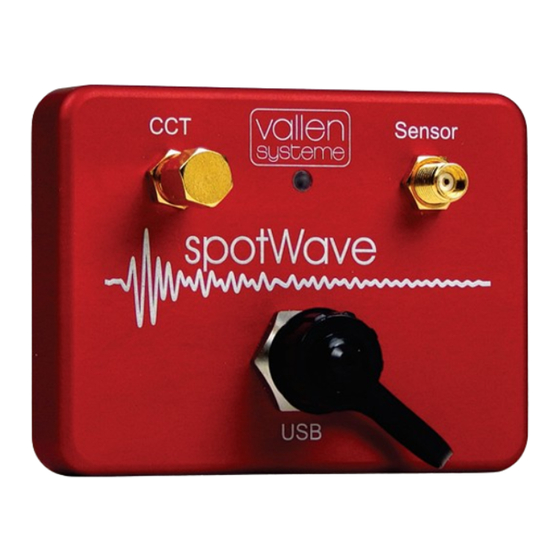
Operating Elements of a spotWave Device Figure 3 shows the front panel elements of a spotWave device. SMA connector CCT SMA connector sensor USB mini-B connector Figure 3: Operation elements of a spoWave device 13.1. USB Mini-B Connector A spotWave device is connected to a mobile device or PC via USB and also powered over it. Property Description USB mini-B female connector... -
Page 18: Sensor Connector (In)
13.3. Sensor Connector (in) The SMA socket labelled Sensor is used to connect an AE sensor to it. Property Description Connector type SMA (IP67), female Input impedance 16 kΩ || 12 pF (±50 mV, ±100 mV input range); 500 kΩ || 940 pF (±5000 mV input range) Input range 94 dB... -
Page 19: Storing, Transporting And Shipping
Storing, Transporting and Shipping A spotWave device is delivered in a special card-board box. It shall be used for storage and transportation since it offers protection against shock. Make sure that the environmental conditions are within specified limits during storage, transportation or shipping of the device. -
Page 20: Installation
Do not continue with installation (or operation) of a device that is visibly damaged. Contact your service technician or Vallen Systeme GmbH for guidance. The environmental conditions at the installation site need to comply with the specified ones. - Page 21 15.2.2. PC Specifications The external PC controls the measurement hardware, runs the system front-end and stores the measurement data. Any kind of PC, e.g. desktop, lunchbox, 19” rack industry standard PC with an USB 3.1 Gen 1 interface can be used. Table 1: Requirements of a PC or laptop that is used as end device for the spotWave device.
-
Page 22: Operating A Spotwave Device
16.2. Connecting a Coupling Check Transducer Only connect a device from Vallen Systeme that is labelled and specified as Coupling Check Transducer (CCT). For connecting the CC-transducer to the spotWave device use the appropriate cable (product code: CBL-1- 1M2-V70). -
Page 23: Measurement Mode
A spotWave device measures features of an AE signal. The measured data is stored to a feature file that meets the SQLite3 standard. The file extension of the feature file is *.pridb. Vallen AE Suite analysis software can read and process this file. -
Page 24: Command Set
The spotWave is a USB CDC (Communications Device Class) device and can be controlled with serial commands. Windows uses the usbser.sys driver by default, which exposes a virtual COM port. If the Vallen AE Suite Software is installed, a setup information file for the spotWave device (C:\Vallen\Drivers\spotWave\vspwv1.inf) is installed to use the low-level and stable winusb.sys driver. - Page 25 16.5.1. States and transitions The executable commands are dependent on the device state. Following diagram shows the possible states and transitions. stop_acq RECORDING [logging = 0] power on [logging = 0] start_acq IDLE [logging = 1] stop_acq LOGGING [logging = 1] 2022-07 file: spotwave_instructions_manual.docx 25 of 50...
-
Page 26: Set_Acq Thr
16.5.2. Commands Overview set_acq thr ................................26 set_acq ddt ................................26 set_acq cont ................................27 set_acq status_interval ............................27 set_acq tr_enabled ..............................27 set_acq tr_decimation ............................27 set_acq tr_pre_trig ..............................27 set_acq tr_post_dur..............................28 set_cct interval ............................... 28 set_data_log enabled ............................. 28 set_datetime ................................ -
Page 27: Commands
set_acq cont Enable/disable continuous mode. Command: set_acq cont 0|1 Valid state: IDLE set_acq status_interval Set interval of status data acquisition. Command: set_acq status_interval <interval> <interval> Interval in ms (0 ~ 2.000.000), 0: disabled Valid state: IDLE set_acq tr_enabled Enable/disable transient data acquisition. Command: set_acq tr_enabled 0|1 Valid state:... -
Page 28: Set_Acq Tr_Post_Dur
set_acq tr_post_dur Set post-duration samples for transient data. Command: set_acq tr_post_dur <samples> <samples> Number of samples (0 ~ 2 * ddt / tr_decimation) µs Valid state: IDLE set_cct interval Set coupling check transmitter / pulser interval in seconds. Command: set_cct interval <interval> <interval>... -
Page 29: Start_Acq
<hp> Highpass cutoff frequency in kHz (0.5 ~ <lp>) <lp> Lowpass cutoff frequency in kHz (<hp> ~ 1000) <order> Filter order {2, 4, 6, 8}, default: 4 Valid state: IDLE start_acq Start acquisition. Acquired data is saved on the device and can be read with get_ae_data and get_tr_data in recording mode or with get_data_log in logging mode. - Page 30 The conversion factor 〈adc2uv〉 is available via the get_info or get_setup command. The conversion factor depends on the input range and gain. Vallen Systeme software uses arbitrary energy units [eu]. A conversion to energy units is done the following = �� � ⋅ �� ⋅ ��...
-
Page 31: Get_Tr_Data
get_tr_data Read transient data sets. The records are deleted from the device memory afterwards. Command: get_tr_data [a] Return data in ASCII format as floats in µV, otherwise ADC values as binary (int16) Valid state: RECORDING | IDLE Response (binary): TRAI=1 T=43686000 NS=768\n <ADC values as binary data (2 * 768 bytes)>... -
Page 32: Get_Data_Log
Command: get_tr_snapshot [a] <samples> Return data in ASCII format as floats in µV, otherwise ADC values as binary (int16) <samples> Number of samples (0 ~ 100.000) Valid state: IDLE The response syntax is the same as for get_tr_data but without TRAI and T in the Response: header line. -
Page 33: Get_Status
adc2uv=1.74\n input_range=94 dBAE\n input_resistance=16 kOhm\n input_capacity=12 pF\n max_samplerate=2 MHz\n analog_bandwidth=20-500 kHz\n cct_voltage=3.3 V\n flash_memory=64 MB\n serial_number=50345\n pcb_vid=200505-06-0123\n verification=2021-01-01 06:41:09.54\n get_status Read status information. Command: get_status Valid state: Response: temp=26 °C\n recording=0\n logging=0\n log_data_usage=1636 sets (0.12 %)\n date=2020-12-17 19:23:40.140\n get_setup Read setup information. Command: get_setup Valid state:... - Page 34 Commands Old command New command set_acq enabled 1 start_acq set_acq enabled 0 stop_acq set_cct <ms> set_cct interval <ms> set_data_log 0|1 set_data_log enabled 0|1 set_filter <hp> <lp> [<order>] set_filter <hp>|none <lp>|none [<order>] get_tr_data [b] get_tr_data [a] (default: ASCII) (default: binary) get_data [b] <samples> get_tr_snapshot [a] <samples>...
- Page 35 16.5.4. Example Recording mode Following example shows how to setup the device and start acquire data. set_filter 80 350 8\n // set 8th order bandpass 80-350 kHz set_acq thr 1000\n // set threshold to 1000 µV / 60 dB(AE) set_acq ddt 400\n // set ddt to 400 µs set_acq cont 0\n // disable continuous mode...
- Page 36 In this case, the spotWave in on COM4. If unsure, just unplug and plug the spotWave’s USB cable while watching the Device Manager. You will see the right COM port disappear and appear again. If the Vallen AE Suite Software is installed, the spotWave is recognized as a “Acoustic Emission Device” using the winusb.sys driver.
- Page 37 Now you are ready to communicate with the device. Test with a simple “get_info” command: 2022-07 file: spotwave_instructions_manual.docx 37 of 50...
-
Page 38: Accessories
Specific accessories for the spotWave device are dedicated cables that fulfill the water tightness requirement. 17.1. Cables It is recommended to use cables from Vallen Systeme GmbH. For information about cables please see separate specification “Accessories for Acoustic Emission Systems” (available on www.vallen.de, on the Vallen AE Suite USB drive, or from sales@vallen.de). -
Page 39: Spotwave Device Extension: Coupling Check Transducer
spotWave Device Extension: Coupling Check Transducer A coupling check transducer (CCT) is an optional extension of the spotWave device. The CCT is not needed for measuring acoustic emission. The CCT is controlled by the spotWave device and can be used to stimulate artificial acoustic emission. -
Page 40: Maintenance
A deteriorated or defective device has to be repaired by Vallen Systeme GmbH before it can be used again. Refer to section “What to do in case of malfunction or damage”. -
Page 41: Compliances Statement
Compliances Statement The spotWave device complies with following directive: • Directive 2014/30/EU (EMC) A spotWave AE measurement system complies with following standard • EN 13477-1 • EN 13477-2 2022-07 file: spotwave_instructions_manual.docx 41 of 50... -
Page 42: Regulations Concerning Redemption And Disposal
Regulations Concerning Redemption and Disposal We, Vallen Systeme GmbH, are registered manufacturer of the measurement instruments (WEEE-Reg.-Nr. DE 68150283). According to German law (§10 subparagraph 2 of Elektro- und Elektronikgerätegesetz – ElektroG) and in the interests of our customers, we accept the obligation for redemption and appropriate disposal of those systems which have been placed by us on the market within the scope of the before mentioned law, after August 13, 2005. - Page 43 Restriction of Hazardous Substances (RoHS) Vallen Systeme GmbH is collaborating with its suppliers to comply with the European Union Restriction of the Use of Certain Hazardous Substances in Electrical and Electronic Equipment (“RoHS”) Directive (2011/65/EU). The RoHS directive prohibits the sale of electronic equipment containing certain hazardous substances such as lead, cadmium, mercury, hexavalent chromium, polybrominated biphenyls (“PBB”) and...
- Page 44 spotWave Device Data Sheet Electrical Properties Electrical property Specification Input range 94 dB , 100 dB or 134 dB ; input range is a hardware option Typical system Input range Peak Noise, A Noise RMS noise 94 dB 34.7 dB 10.36 V (20-500 kHz) 100 dB...
- Page 45 1 eu = 10 V²s Processing Performance Performance Specification Minimum guaranteed 100 hits/s with Vallen Systeme’s spotWave Acquisition software hit rate Hit buffer 200 hit data sets in Acquisition Mode Logging buffer 64 MB, approximately 1.3 million hit data sets 2022-07 file: spotwave_instructions_manual.docx...
- Page 46 Maximum samples 100 k samples with Vallen Systeme’s Acquisition software; 200 k samples total. per record Pretrigger Selectable, maximum of 2 k samples 2022-07 file: spotwave_instructions_manual.docx...
- Page 47 Worldwide Representatives AS E AN c oun t r ie s: Si ngap or e , M al a ys ia , T h ai l an d , In d o n e si a NDT Instruments Pte Ltd No 50, Ubi Avenue 3, #05-20, Frontier Singapore 408866 Singapore...
- Page 48 Chin a CST Beijing Crahesion Science & Trade Co. Ltd. Shijingshan District Room 1113, Zeyang Building, No.166 Fushi Road Beijing 100043 P. R. China telephone: 0086-10-8890 99 50 /51 /52 /53 F r an ce ACTION-NDT Rue des Chênes - ZA des Brugues 82410 SAINT ETIENNE DE TULMONT FRANCE telephone: +33 (0)5 82 73 01 06...
- Page 49 Net he rl an ds MCB Techniek Vossiusstraat 25 2984 GS RIDDERKERK NETHERLANDS telephone: +31 180 85 50 23 mail: marco@mcbtechniek.nl Po la nd EC TEST Systems Sp.z o.o. ul. Cieplownicza 28, 31-574 KRAKOW POLAND telephone: +48 12 627 77 77 mail: biuro@ects.pl Rom an ia Total Control S.R.L.
- Page 50 Boundary House, Boston Road London W7 2QE United Kingdom telephone: 0044 208 089 8483 If you are not within a territory served by a Vallen Systeme GmbH representative, pick up contact with Vallen Systeme GmbH headquarter in Germany, directly. 2022-07 file: spotwave_instructions_manual.docx...
Need help?
Do you have a question about the spotWave 201 and is the answer not in the manual?
Questions and answers