Table of Contents
Advertisement
Quick Links
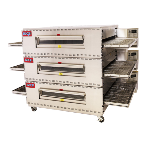
EDGE 1830
EDGE
EDGE 2440, 3240
EDGE
EDGE 2460, 3260, 3260S
EDGE
EDGE 3860, 4460, 4460S
EDGE
E D G E 3 2 7 0 , 3 8 7 0
E D G E
Operation & Service Manual
MF&B RESTAURANT SYSTEMS, INC.
119 ICMI RD, STE 300, DUNBAR, PA, 15431 USA
(1)888.480.EDGE
(1)724.628.3050
SUPPORT@EDGEOVENS.COM
1830
2440, 3240
2460, 3260, 3260S
3860, 4460, 4460S
3 2 7 0 , 3 8 7 0
Original Installation
(2C) Chassis, 2022
US Domestic
Retain This Manual for Future Reference
To Be Service by Authorized & Qualified Personnel Only
CD-941-407-3
WWW.EDGEOVENS.COM
Advertisement
Table of Contents

Summary of Contents for MF&B Restaurant Systems EDGE 1830
- Page 1 EDGE EDGE 1830 1830 EDGE EDGE 2440, 3240 2440, 3240 EDGE EDGE 2460, 3260, 3260S 2460, 3260, 3260S EDGE EDGE 3860, 4460, 4460S 3860, 4460, 4460S E D G E E D G E 3 2 7 0 , 3 8 7 0...
- Page 2 PROUDLY BUILT IN THE USA MF&B Restaurant Systems, Inc. 119 ICMI RD, STE 300 Dunbar, PA 15431, USA 724.628.3050 (telephone) 724.626.0247 (fax) sales@edgeovens.com www.edgeovens.com Valued customer, We thank you for the opportunity to provide you with, what we believe to be, the finest conveyor oven available on the market today.
- Page 3 Service policy All service technicians of the EDGE Oven must read this summary and all warnings and cautions in the manual. Any internal part(s) replacement or assembly and reassembly must be performed by qualified service person- nel with a good understanding of mechanical, gas and electrical components. If difficulties arise in locating a qualified service person, please contact your EDGE oven distributor or MF&B for assistance in locating qualified personnel to assist you.
-
Page 4: Table Of Contents
Ta b l e o f C on te nts WARNING AND SAFETY INFORMATION ............... i SPECIFICATIONS ....................1 Export, Gas Configuration Data ......................1 North America, Gas Configuration Data ...................2 Dimensions ............................3 OVEN COMPONENTS ..................4 INSTALLATION INSTRUCTIONS ................5 Foreword ............................5 Tools &... - Page 5 WIRING DIAGRAM ..................... 37 PART IDENTIFICATION ..................38 GAS CONVERSION ................... 39 Removing the Gas Train .........................39 Replacing the Main Orifice ......................39 Replacing the Pilot Orifice ......................40 Replacing the Gas Valve ........................40 Installing the Gas Train ........................40 Adjustment Air Shutter ........................41 Gas Type Markings .........................41 TROUBLESHOOTING ..................
-
Page 6: Warning And Safety Information
P R E FA C E W A R N I N G AN D SA F ETY I NFORMATION WARNING Do not store or use gasoline, cleaning solvents, or any other material that may emit flam- mable vapors near this or any other appliance. WARNING Improper installation, adjustment, alteration, service, or maintenance can result in prop- erty damage, injury, or death. - Page 7 P R E FA C E NOTICE The oven electrical wiring diagram is located inside the control compartment. IMPORTANT US CUSTOMERS Oven installation must comply with local codes or, if local codes do not exist, with the National Fuel Gas Code, ANSI Z223.1/NFPA 54. This appliance must be electrically grounded in accordance with local codes, or if local codes do not exist, with the National Electrical Code, ANSI/NFPA 70.
- Page 8 P R E FA C E IMPORTANT NORTH AMERICA CUSTOMERS OVENS EQUIPPED WITH CASTERS: 1. When this appliance is installed with casters, it must be installed with the casters sup- plied, a connector complying with ANSI Z21.69 (CSA 6.16), a quick-disconnect device complying with ANSI Z21.41 (CSA 6.9), and a mechanism to limit movement of the appliance without straining the connector or its associated piping system.
- Page 9 P R E FA C E General cautions WARNING Indicates conditions that could lead to injury or death. CAUTION Indicates conditions that could damage equipment or property. CAUTION Indicates conditions that may result in a burn injury. General Warnings Warnings indicate conditions or practices that could lead to injury or death. Warnings related to the operating environment WARNING To avoid a possible explosion, do not service the product in an atmosphere where explo-...
- Page 10 P R E FA C E Electrostatic discharge (ESD) CAUTION Electrostatic discharge (ESD) can damage or destroy electronic components. Handle stat- ic-sensitive components using safe practices. CAUTION Assume that all electrical and electronic components of the appliance are static sensitive. Electrostatic discharge is a sudden current flowing from a charged object to another object or to ground.
-
Page 11: Specifications
S P E C I F I C AT I O N S SPE C I F I CAT I ONS Export, Gas Configuration Data Supply Pressure (mbar) Category Destination Country (Export AT-CH-CY-CZ-DK-EE-ES-FI-FR-GB-GR-HR-HU-IE-IT-LT-LU-LV-NO-PT-RO-SE-SI-SK-TR DE-PL-RO RO-NL BE-FR 20; 25 BE-CY-ES-FR-GB-GR-HU-IE-PT 30; 28-30 DE-FI-NL-RO BE-CH-CZ-ES-FR-GB-GR-IE-IT-LT-NL-PL-PT-SI-SK AT-BE-CH-CY-CZ-DE-DK-EE-FI-GB-GR-HU-IT-LT-NL-NO-PL-RO-SE-SI-SK-TR... -
Page 12: North America, Gas Configuration Data
S P E C I F I C AT I O N S North America, Gas Configuration Data Model Manifold Shutter (Air) Heating Gas Type Supply Pressure Orifice High-Fire / Low-Fire Opening EDGE-1830 Natural 6”w.c. ~ 8”w.c. 0.1405 in. 4.5 inW.C. Natural 6”w.c. -
Page 13: Dimensions
S P E C I F I C AT I O N S Dimensions When installed as: Measurements are in inch unless otherwise noted Sin- Dou- EDGE EDGE EDGE EDGE EDGE EDGE EDGE EDGE EDGE Detail Triple 1830 2440 3240 2460 3260 3860... -
Page 14: Oven Components
I N S TA L L AT I O N OV E N C OM PONENTS 1. Control Can Assembly: Houses the operat- ing controls for the oven and the natural gas control devices and burner. 2. End Plug, Upper: Closes off the top half of the bake chamber, above the conveyor belt. -
Page 15: Installation Instructions
I N S TA L L AT I O N I NSTAL LAT I O N I NSTRUC T IONS IMPORTANT REQUIREMENTS Oven installation must comply with local codes or, if local codes do not exist, with the National Fuel Gas Code, ANSI Z223.1/NFPA 54 -OR- Natural Gas Installation Code, CAN/CGA-B149.1, or the Propane Gas Installation Code, CAN/CSA-B149-2, as applicable. -
Page 16: Tools & Equipment Required
I N S TA L L AT I O N Tools & Equipment Required LIFTING SYSTEM (2) EDGE Lifting Jacks, PN: IE-9001, Genie Lift or similar lifting system (1) EDGE installation cart, PN: IE-9201, 4-wheel cart, pallet jack, or similar. (1) 10ft, SCH40 steel pipe, 3”... -
Page 17: Stacking Ovens
I N S TA L L AT I O N HAND TOOLS (1) #2 Phillips Screwdriver (1) Ratchet and short extension (1) 5/16” Socket or nut driver (1) 7/16” wrench (1) 9/16” Socket (1) 3/8” Socket or wrench *oven back (1) Tin snips for cutting banding (1) Adjustable wrench (Crescent) *as needed Stacking Ovens... - Page 18 I N S TA L L AT I O N 4. Install the supplied belt frame hinge using the previously removed hardware. 5. For Triple Stacked ovens, the casters are to be fastened directly to the bottom oven base. Single and Double Stacked ovens, the casters are to be attached to the supplied legs, which will then be attached to the bottom oven base.
- Page 19 I N S TA L L AT I O N 6. Remove the fasteners from the pallet shipping bracket. 7. With the belt now straight and assembled and the oven released from the pallet, pass the 3” O.D. Schedule 80 pipe through the lifting plates and the oven body. 8.
- Page 20 I N S TA L L AT I O N 9. Stacking ovens in a Double or Triple Stack requires enough room for the base oven to be moved clear of your work area. Simply repeat the process for each additional oven, continuing the lift until each additional oven clears the height of the oven stack.
- Page 21 I N S TA L L AT I O N 11. The oven(s) can then be pushed under the suspended oven and lowered onto the stack. WARNING Do not place your hands or fingers under the connecting lip. The edge of the connecting lip is sharp and can cause severe cuts or amputation.
-
Page 22: End Plug Removal & Inspection
I N S TA L L AT I O N 12. Once the ovens are stacked, begin removing the lifting plates. Remove the lower wingnuts from the end plugs and pull the lifting plate from the oven. Repeat for all lifting plates. Install the wingnuts once the lifting plates are removed. -
Page 23: Conveyor Drive System
I N S TA L L AT I O N Conveyor Drive System The conveyor motor shaft and sprockets bore are 1/2”, keyed. The sprocket for the motor(s) are: Standard, single conveyor system - 10 tooth, 35 pitch, (2x Allen set screws) Split-Belt, dual belt system - 15 tooth, 25 pitch, (2x Allen set screws) Motor sprocket orientation for the rear-most motor is flipped on a split-belt system: Standard Rear Motor... - Page 24 I N S TA L L AT I O N oven belt direction is NOT NEEDED. The conveyor belting tension must be adjusted over time. To make this task easier, beginning January 2022, the left (non-drive side) of the belt frame incorporates adjustment brackets. Adjustment set A is for use with Split-Belt conveyors.
-
Page 25: Standard Accessories
I N S TA L L AT I O N Standard Accessories The standard accessories supplied with your new oven(s) may include: Heat Shields (REQUIRED for operation of stacked ovens) Chain Guards Perforated Crumb Pans (For middle or top ovens) Non-Perforated Crumb Pans (For lower or single ovens) Belt Stops (For exit side of all ovens) Additional Collimating Panels or accessories may come with the oven(s), please refer to the instruction... -
Page 26: Finger Assemblies
I N S TA L L AT I O N Finger Assemblies 1. All EDGE ovens are shipped with (8) or (14) finger assemblies per oven. Each finger assembly consists of three (3) parts: A) Finger Housing B) Collimating Panel (various configurations) C) Finger Cover 2. -
Page 27: Collimating Panels
I N S TA L L AT I O N Collimating Panels EDGE Original Installation, Operation and Service Manual... -
Page 28: Restraint Cable
I N S TA L L AT I O N Restraint Cable All EDGE ovens are equipped with casters. A restraint cable must be installed to limit movement of the oven without straining the gas or electrical connections. One end of the restraint cable is to be anchored to the wall, the other end is anchored to the supplied eyelet bracket. -
Page 29: Valve Specifications
I N S TA L L AT I O N WARNING Always check for leaks after making any gas supply piping connections or performing any ser- vice on the oven. Leak testing is required during installation. Gas Inlet pressures must not exceed 37 mbar / 14.8 inW.C. In the event the supply pressure is greater, a gas regulator must be installed at each appliance. -
Page 30: Manifold Adjustment
I N S TA L L AT I O N Manifold Adjustment The MANIFOLD is to be adjusted to the Region Specifications and gas type provided earlier in this manual. *Damaged gas valves are NOT covered under the limited warranty. •... -
Page 31: Warranty Activation
I N S TA L L AT I O N Warranty Activation It is important that the installed oven(s) are properly commissioned and the record of the commission- ing be recorded. Provided with this documentation you will find a “START-UP CHECKLIST”. Please complete and mail this document you may send a scanned copy to warranty@edgeovens.com. -
Page 32: Oven Operation
O P E R AT I O N OV E N O PE R ATION Oven Start-Up 1. Turn the MAIN POWER switch to ON. 2. Touch and hold the POWER Icon for three (3) seconds. 3. Set temperature to the desired baking temperature. 4. -
Page 33: Menu System
O P E R AT I O N Manual Operation Manual operation is needed to actively adjust the Time and Temperature of the oven. This mode is protected by the Customer PIN. Touch the recipe name above the displayed temperature for 2 seconds and release. -
Page 34: Advanced Operation
O P E R AT I O N Advanced Operation Selecting a Recipe Touch and hold the recipe name space on the display for 1-2 seconds. Select the desired recipe using the UP/DOWN arrows, touch CHECK to accept. Create a New Recipe: You may store up to 30 recipes. - Page 35 O P E R AT I O N Deleting a Recipe Selecting the recipe (see Change Recipe). Touch and hold the recipe name space on the display until a PIN entry screen appears. Customer PIN is required. In the Name space adjustment, select ‘<DEL RCP>’.
- Page 36 O P E R AT I O N Recipe Download This feature will save the recipes stored within the control system on a USB Thumb drive. Remove the USB dust cover, located near the control cabinet, cooling fan. Insert a USB thumb-drive in the USB connector.
-
Page 37: Preventative Maintenance
O P E R AT I O N PR EV E N TATI V E M AI NTENANC E NOTICE MF&B Restaurant Systems, Inc. assumes NO responsibility or liability for equipment damage, property damage, bodily injury, or incident claims related to the application of Preventative Maintenance. PREVENTATIVE MAINTENANCE, PURPOSE It is good practice to develop and execute a strict preventative maintenance schedule for ALL equipment utilized within your business operations. - Page 38 O P E R AT I O N OVEN CLEANING, CRUMB TRAYS Frequency: Surface areas of the equipment should be wiped clean daily. Method: Use a solution of mild dish detergent and water for normal cleaning. Wipe the surface using a soft cloth. Crumb trays may be submerged for cleaning.
- Page 39 O P E R AT I O N MAINTENANCE, 4” COOLING FAN Frequency: The 4” cooling fan maintains a steady supply of ambient temperature air to the control system and should be maintained as needed or minimally once a month. Method: Locate the 5”x5”...
- Page 40 O P E R AT I O N The burner assembly is comprised of: the burner tube, venturi, and pilot burner. The spark electrode and flame rod and connected to the pilot burner. The optical flame detector is mounted to the burner tube. The ignition spark originates from the electrode and arcs to the pilot burner.
- Page 41 O P E R AT I O N sense wire from the respected terminals. Be mindful of live electrical components when test firing the appli- ance, use care and good practices. It is recommended that the cabinet be closed during normal operation. MAINTENANCE, FLAME MONITOR Frequency: EDGE Conveyor Ovens, produced from 2019, are equipped with an advanced flame monitoring system.
-
Page 42: Service Operation
S E R V I C E SERV I CE O P E RATI ON Service Menu: - Swipe the control screen Left or Right to access the Menu System. - Touch the GEAR icon to enter the Settings Menu, Service PIN is required (6453). - Use UP/DOWN arrows to navigate to ‘SERVICE’, select. -
Page 43: Service Tools & Material
S E R V I C E SERV I CE TOOLS & M ATERI AL This list may not cover all scenarios. Please use best judgment and practices For effective repairs, have available a general tool sets available 1/4” or 3/8” Drive Socket Set {SAE - 3/16”, 7/32”, 1/4”, 5/16”, 11/32”, 3/8”, 7/16”, 1/2”, 9/16”; MM - 5, 6, 7, 8, 9, 10, 11, 12, 13;... -
Page 44: Sequence Of Operation
S E R V I C E SEQ U EN C E O F OPER ATI ON Part references, terminal, plugs and plug pins should be referenced with the wiring diagram. STEP OPERATIONS TEST POINTS MAIN POWER switch OFF and the Control System OFF Two-piece MAIN POWER switch: Switch 1, S1 and Switch 2, S2 PS(N) Wht –... - Page 45 S E R V I C E Fan Blade of M1 rotates, plenum pressure rises PS(N) -Wht – AS1 Rd/Wh AS1 closes, MAINS passes to 24Vac Transformer, T1 MAINS Vac Chassis Ground – MCP9(6) Org T1 will then supply 24Vac to MC P9(6) “proof-of-air” 24 Vac PS(N) Wht –...
-
Page 46: Edge G2, Control Module Pinout
S E R V I C E (Shutdown Option 1) Cooldown triggered by POWER ICON touch Conveyor system stopped, MC P6 de-energized M4 shuts down Chassis Ground – MCP9(3)(N) MC P9(3) de-energized, removing power from burner 0 Vac Oven cools to 223F R1(0) Brw –... -
Page 47: Wiring Diagram
S E R V I C E W I R I N G D IAG RAM EDGE Original Installation, Operation and Service Manual... -
Page 48: Part Identification
S E R V I C E PART I DE N T I F I C ATI ON USB Port........135063 Cooling Fan.....135130, 135134 24VDC Power Supply....135140 Air Switch........135145 *Frequency Drive, if equipped......(CE)135142, (US,CA,MX)135142-120, (ALL)135142-120/240 Induction Blower......135120 Induction Fan(not shown)....135123 *Conveyor Motor(not shown)..135148 Gas Valve....135108-xxx.xxx-REP Optical Detector......135049... -
Page 49: Gas Conversion
S E R V I C E GA S CO N V ER SI ON *The BASO combination gas valve contains a bypass orifice which is not EDGE approved for field replacement. Gas conversions require replacement of the BASO combination gas valve, Main orifice, and the adjustment of the air shutter. -
Page 50: Replacing The Pilot Orifice
S E R V I C E Replacing the Pilot Orifice The pilot orifice must match the gas type. A 7225 orifice is used for Propane, while a 3239 is used for Natural. • Disconnect the Blue electrode wire from the pilot assembly attached to the Venturi. • Remove the (2) Phillips screws from the pilot assembly. -
Page 51: Adjustment Air Shutter
S E R V I C E Adjustment Air Shutter Air Shutter Settings Gas Type Shutter Gas Type Shutter NATURAL E1830: 1, Others: 1.5 G20/G25 PROPANE G30/G31 Shutter Style 1, Induction Blower Shutter Style 2, Induction Fan Gas Type Markings The valve will be marked with the correct fuel type and adjustment. -
Page 52: Troubleshooting
S E R V I C E TR O U B L ESH OOTING Basics First The G2 Control System stores component I/O, user adjustments, and any errors (seen or unseen) which have occurred over a 14 - 21 day period. Please use the EXPORT function of the oven and send the Logfile(s) to support@edgeovens.com for evaluation and diagnosis. -
Page 53: G2 'Diagnostic' Lamp
S E R V I C E Symptom Possible cause Possible correction Check for 5VDC between P6.10 (Red/Wht) and P6.9 (Black). Missing Tach Pickup If missing, replace the Control Board This condition produces a “Belt Low Speed” error. Measure DCV between P6.9 (Black) to P6.5 / P6.4 / P6.3. If a mea- surement is 5VDC, the motor is bound. -
Page 54: G2 Control System Messages
S E R V I C E G2 Control System Messages The EDGE oven has sophisticated diagnostic and error logging ability which can store about 21 days of operation data. For the most effective and complete diagnostics of the system, review the “Advanced Operation”... - Page 55 S E R V I C E ALARMS (Will auto-reset as condition is resolved, oven will continue to operate) Error Name Display Line 1 Display Line 2 Error Trigger Possible Cause The flame signal was lost or Main Valve power is not not detected;...
- Page 56 S E R V I C E FAULTS (Will result in system shutdown, will not auto-reset) Error Name Display Line 1 Display Line 2 Error Trigger Possible Cause Air switch is bypassed, or the air Safety circuit is closed “Air Switch Not “Closed Before switch has shorted.
-
Page 57: Part Failure Verification
S E R V I C E PA RT FA I LU R E V ER IF IC AT ION All attempts have been made to provide solid information and techniques to verify that a suspect part has in fact failed. - Page 58 S E R V I C E ly inspect the ignition electrodes and flame rod for buildup, clean as needed. Use 220 grit sandpaper to clean the electrodes. NEVER use metallic materials to clean the electrodes, this will degrade them. The pilot head must also be cleaned.
- Page 59 S E R V I C E Thermocouple The Thermocouple is located between the bottom finger 2 & 3 (or 5 & 6 on S & 70” models). The baking chamber will be slightly lower than the displayed temperature, due to the point of measurement. A 10°F offset is used in the control to decrease this variation.
-
Page 60: Type-J Thermocouple Chart
S E R V I C E TY P E- J T H ER M OCOUPLE C HART Formula: (Actual Temp)mV = (Ambient Temp + 10)mV + (Measured)mV (Measured)mV = Measured value of thermocouple with oven at stable temperature. (Ambient Temp)°F = Ambient temp of control PCB (back of control cabinet door). (Displayed Temp)°F = Temperature displayed on control UI. -
Page 61: Thermocouple Worksheet
S E R V I C E Thermocouple Worksheet Ambient Temperature =_______ °F __________ mVDC (D) Displayed Temperature - 10 _______ °F offset (M) Measured Thermocouple =_______ mVDC mVDC ____________ + ____________ + (M) mVDC mVDC ____________ (ACTUAL) *Convert using chart Deviation ______ °F - (D) _____ °F = _________ °F (ACTUAL) -
Page 62: Part List
S E R V I C E PA RT L I S T Part No. Description Part No. Description 135142-120 135001.G2 4pc Power Switch 120V/240V (Invertek) (All Regions) /240 135003-BK 3A Breaker 135145 Air Switch 135004-BK 10A Breaker 135148 24Vdc BLDC Conveyor Motor (Extended harness) 135008 OTP Thermostat 135156... - Page 63 REVISION HISTORY 12/12/2022 rev 2 Addition of note regarding Blower Speed monitoring, page 46 03/27/2023 rev 3 Corrections of NAT Air shutter settings...
Need help?
Do you have a question about the EDGE 1830 and is the answer not in the manual?
Questions and answers