Table of Contents
Advertisement
Quick Links
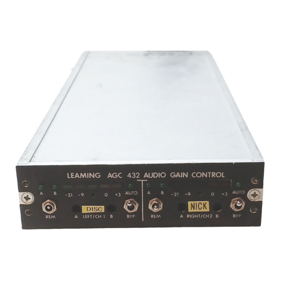
LEAMING INDUSTRIES AGC432
STEREO/DUAL MONO
AUTOMATIC GAIN CONTROL
INSTRUCTION BOOK
IB 173432-21B
ALL ENGINEERING DESIGNS, DRAWINGS AND DATA CONTAINED HEREIN ARE
PROPRIETARY. NO PART OF THIS BOOK MAY BE COPIED OR OTHERWISE USED
WITHOUT WRITTEN AUTHORIZATION
COPYRIGHT MARCH 1992
BY
LEAMING INDUSTRIES
15339 BARRANCA PARKWAY
IRVINE, CALIFORNIA 92718
(714) 727-4144
March, 1992
AGC432
PAGE 1
Advertisement
Table of Contents

Summary of Contents for LEAMING INDUSTRIES AGC432
- Page 1 LEAMING INDUSTRIES AGC432 STEREO/DUAL MONO AUTOMATIC GAIN CONTROL INSTRUCTION BOOK IB 173432-21B ALL ENGINEERING DESIGNS, DRAWINGS AND DATA CONTAINED HEREIN ARE PROPRIETARY. NO PART OF THIS BOOK MAY BE COPIED OR OTHERWISE USED WITHOUT WRITTEN AUTHORIZATION COPYRIGHT MARCH 1992 LEAMING INDUSTRIES...
-
Page 2: Table Of Contents
APPENDIX COMPONENT LOCATOR DIAGRAM WARNING The AGC432 is powered by 120 volts AC. Contact with 120 volts can cause injury or death. Disconnect the AGC432 from electric power before opening the cover. Refer service and internal adjustments to qualified personnel. -
Page 3: Introduction
The AGC432 includes a programmed gain controller. When the audio level falls over 20 dB below normal, the AGC432 assumes that there is a pause in the program and holds its gain setting for 10 seconds. This maintains the ambient background levels in their original perspective during brief program pauses. - Page 4 However, you may wish to configure it differently for your application. If not, you may skip this section and proceed to the Installation section. The AGC432 may be configured for either dual mono, or true stereo, or synthesized stereo. This may be done by connecting jumpers to the control connector on the rear panel, as detailed below.
- Page 5 Refer internal adjustments to qualified personnel. The AGC432 may be configured to any one of three gain control slopes (2:1, Constant Output, or Adaptive Slope) by positioning jumper jacks on quads of pins on the circuit board. The four pins arranged in a quad on the left half of the board (as you look down from the front) are for the left channel (Channel 1);...
-
Page 6: Installation
Refer internal adjustments to qualified personnel. The AGC432 may be configured to any one of three release times (10, 15, or 25 seconds). The release time can be set by positioning jumper jacks on a row of three pins on the circuit board. -
Page 7: Connectors, Screw-Terminal Plug Blocks
The AGC432 is intended to be mounted on a Leaming PMU401 Mainframe. Each unit requires one-third of the PMU401. To mount the AGC432 in a PMU401, remove the blank front plate (if any) from the PMU401, place the AGC432 in the selected position, and secure it with the four #6-32 screws provided. -
Page 8: Audio Output Connection
"A" input, with the exception that it is plugged into the "B" Input connector on the back of the AGC432 (rather than Input "A"). See Section 4.2 for information regarding the selection of A/B inputs and stereo synthesis. -
Page 9: Audio Input Level Setting
It is convenient to use an input level control of the AGC432 to do this; just re-set this control as outlined above when the demonstration is completed, in order to set the AGC432 into its optimum range. -
Page 10: Audio Input Selection (Ad Insertion)
In the REMote position of the A/REM/B selector switch, when terminal A/B CH 1 (pin 6) or A/B CH 2 (pin 5) is grounded, the AGC432 switches that channel from Input "A" to Input "B". The front panel A/REM/B switch will override any remote control connections on the back panel if placed in either the "A"... -
Page 11: Videocipher Backup Audio With Stereo Synth
VideoCipher's Bypass N.O. terminal (pin 8 of TB1) to the AGC432's "SYNTH" terminal (#3), and run the other control wire from the VideoCipher's Bypass COM terminal (pin 9 of TB1) to the AGC432 Ground terminal (#2). -
Page 12: Theory Of Operation
THEORY OF OPERATION WARNING The AGC432 is powered by 120 volts AC. Contact with 120 volts can cause injury or death. Disconnect the AGC432 from electric power if it is necessary to open the cover. Refer service and internal adjustments to qualified personnel. - Page 13 Because of this, the indicated peak level of a steady tone is lower than that of typical program material at the match-level point of the AGC. Level sensing, control, and limiting in the AGC432 is done following 75 microsecond pre-emphasis, which matches the pre-emphasis used in most transmitters.
-
Page 14: Performance Evaluation
BYPass mode. PERFORMANCE EVALUATION When verifying performance specifications of the AGC432, be sure that none of the features interfere with the item being tested. Specifically, single-tone frequency response tests should run in the BYPass mode and at a level approximately 20 dB below 100% modulation. -
Page 15: Specifications
SPECIFICATIONS NOTE: All audio levels are in dB re 0.775 V & 1000 Hz (0 dBm OVERALL PERFORMANCE AUDIO OUTPUT FREQUENCY RESPONSE: OUTPUT LEVEL, PEAK: 20 Hz to 15 kHz, 0.5 dB +10 dB +8/-10 dB ± adjustable internally DISTORTION: 0.3% maximum THD OUTPUT IMPEDANCE: 60 ohms, balanced...