Table of Contents
Advertisement
Quick Links
Advertisement
Table of Contents

Related Manuals for Rockchip RK3588 EVB

Summary of Contents for Rockchip RK3588 EVB
- Page 1 RK3588 EVB User Guide Releaseversion:V1.0 Releasedate:2022-1-25...
- Page 2 Brand Statement "Rockchip" and "瑞芯微" , "瑞芯"and other Rockchip trademarks are trademarks of Rockchip Electronics co., ltd., are exclusively owned by Rockchip Electronics Co., Ltd. All other trademarks or registered trademarks mentioned in this document are owned by their respective owners.
- Page 3 RK3588 EVB User Guide Preface Preface Overview This guide mainly introduces the basic functions and hardware features, multi-function hardware configuration, and software debugging operation methodsof RK3588EVB. It aims to help debuggers use RK3588EVB befaster and more accurately, and be familiar with RK3588 chip development and application solutions.
- Page 4 RK3588 EVB User Guide Revision History Revision History This revision history recorded description of each version, and any updates of previous versions are included in the latest one. Version Author Revision Date Revision Description Remark V1.0 2022-1-6 Initial release Copyright @ 2022Rockchip Electronics Co., Ltd...
- Page 5 RK3588 EVB Uses Guide Acronyms Acronyms Acronyms include the abbreviations of commonly used phrases in this document: Abbreviation English meaning Chinese meaning 中央处理器 Central Processing Unit 神经网络处理器 Neural Network Processing Unit 视频处理器 Video Processing Unit 双倍速率同步动态随机存储器 Double Data Rate 内嵌式多媒体存储卡...
-
Page 6: Table Of Contents
RK3588 EVB User Guide Contents Contents Preface ....................................II Contents .................................... V Figures ................................... VII Tables ....................................IX System Introduction ..............................1 RK3588 Introduction ............................1 RK3588 Chip Block Diagram ..........................2 System Framework ............................2 1.3.1 System Block Diagram ..........................2 1.3.2... - Page 7 RK3588 EVB User Guide Contents 3.18 HDMI Output Interface ............................ 29 3.19 HDMI Input Interface ............................30 3.20 Fan Power Connector ............................30 3.21 Sensor Module Expansion ..........................31 3.22 Speaker Interface.............................. 32 Precautions ................................33 Copyright @ 2022Rockchip Electronics Co., Ltd...
-
Page 8: Figures
Figure 1-11 ADB Connection is Normal ......................... 11 Figure 2-1 RK3588 EVB Picture ..........................12 Figure 2-2 RK3588 EVB Block Diagram ........................ 13 Figure 2-3 Pitch 0.8mm Vertical Double Row 80 PIN PCB Package ..............15 Figure 3-1 DC12V Input, Front-end Buck Converter and PMIC Chip ..............16 Figure 3-2 Location of LPDDR4x and eMMC ...................... - Page 9 RK3588 EVB User Guide Figures Figure 3-24 IMX415 Module Board ........................31 Figure 3-25 SPK Socket ............................32 Copyright @ 2022Rockchip Electronics Co., Ltd VIII...
-
Page 10: Tables
RK3588 EVB User Guide Tables Tables Table 1-1 PCB Functional Interface Introduction Table ................... 4 Table 2-1 Correspondence Table of Peripheral Address and IO Level Value Mounted on I2C Channel ....13 Table 3-1 MIPID/CPHY_RX Signal Definition Table .................... 24 Table 3-2 MIPI DPHY_RX Signal Definition Table .................... -
Page 11: System Introduction
RK3588 EVB User Guide System Introduction 1 System Introduction 1.1 RK3588 Introduction RK3588 is a high-performance, low-power application processor chip. It integrates 4 Cortex-A76, 4 Cortex-A55 and independent NEON coprocessor. Suitable for ARM PC, edge computing, personal mobile Internet devices and other multimedia products. -
Page 12: Rk3588 Chip Block Diagram
1.3 System Framework 1.3.1 System Block Diagram RK3588 EVB system uses RK3588 as the core chip of the system, and two power supply schemes, RK806-2 dual PMIC or RK806-1 single PMIC can be selected. Use LPDDR4X, eMMC, MIPI TX, and SATA/PCIe and other functional external device interfaces to integrate a stable and mass-produced solution. -
Page 13: Function Summary
Slave Pmic2 RK806-2 Figure 1-2RK3588 EVB1 System Block Diagram 1.3.2 Function Summary RK3588 EVB includes the following functions: DC Power: DC 12V adapter power supply interface; TYPEC: One complete TYPEC interface, compatible with system firmware upgrade channel and DP1.4 output interface;... -
Page 14: Functional Interface
RK3588 EVB User Guide System Introduction Audio Interface:Support speaker, earphone output sound, single MIC recording SATA3.0Interface: Two 7pin SATA interface PCIe3.0 Interface: One standard PCIex4 interface, used to expand PCIe devices; UART Debug: User debugging to view the LOG information; support TYPEC and MINI USB interface;... -
Page 15: Function Module Layout
RK3588 EVB User Guide System Introduction 1.3.4 Function Module Layout EVB1 functional interface distribution diagram: Figure 1-3EVB1 Functional Interface Distribution Diagram(front) Figure 1-4EVB1 Functional Interface Distribution Diagram(back) Copyright @ 2022Rockchip Electronics Co., Ltd... -
Page 16: Module
RK3588 EVB User Guide System Introduction 1.4 Module The RK3588 EVB kit includes the following items: RK3588EVB Power adapter, default specification: input 100V AC~240V AC, 50Hz; output 12V DC, 3A Display, specification: MIPI; size: 5.5 inches/vertical screen; resolution: 1920*1080 ... -
Page 17: Firmware Upgrade Method
RK3588 EVB User Guide System Introduction 1.6.2 Firmware Upgrade Method There are two ways to upgrade RK3588 EVB firmware: Enter Loader upgrade mode: Before the system is powered on, SARADC_IN1 needs to be kept low, and the system will enter the Loader state. -
Page 18: Figure 1-7Schematic Diagram Of Entering Maskrom Programming Mode
RK3588 EVB User Guide System Introduction Before the system is powered on, SARADC_IN0 is low and enters the MASKROM state. Specific steps are as follows: Connect the TYPE_C port to the computer, press and hold the MASKROM button on the board. -
Page 19: Serial Debugging
RK3588 EVB User Guide System Introduction 1.7 Serial Debugging 1.7.1 Serial Port Tool Connect the MINI USB Debug debugging interface of the development board to the the computer, and get the current port COM number in the device manager of the PC end. -
Page 20: Figure 1-9Serial Port Tool Configuration Interface
RK3588 EVB User Guide System Introduction Figure 1-9Serial Port Tool Configuration Interface Copyright @ 2022Rockchip Electronics Co., Ltd... -
Page 21: Adbdebug
RK3588 EVB User Guide System Introduction Figure 1-10Serial Port Tool Debug Interface 1.7.2 ADBDebug Ensure that the driver is installed successfully, and the PC is connected to the TYPE_C port on the same side as the power supply of the development board;... -
Page 22: Hardware Introduction
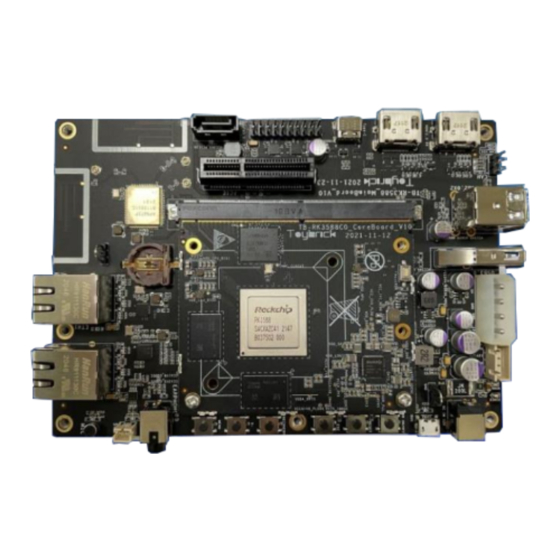
RK3588 EVB User Guide Hardware Introduction 2 Hardware Introduction 2.1 The Pictures Figure 2-1RK3588 EVBPicture Copyright @ 2022Rockchip Electronics Co., Ltd... -
Page 23: Power Block Diagram
RK3588 EVB User Guide Hardware Introduction 2.2 Power Block Diagram Figure 2-2 RK3588 EVB Block Diagram 2.3 I2CAddress The development board reserves a wealth of peripheral interfaces. The user debugging I2C peripherals will involve I2C channel multiplexing. Table 2-1 shows the I2C address and level values corresponding to the existing development board devices. -
Page 24: Extension Connector Information
RK3588 EVB User Guide Hardware Introduction 2.4 Extension Connector Information In actual use, the user may make an expansion board. The model of the development board connector is as follows: U4600 and U4700 are vertical double-row 80PIN card sockets with 0.3mm pins and 0.8mm spacing. The dimensions are as follows: Copyright @ 2022Rockchip Electronics Co., Ltd... -
Page 25: Reference Diagram
RK3588 EVB User Guide Hardware Introduction Figure 2-3Pitch 0.8mm Vertical Double Row 80 PIN PCB Package 2.5 Reference Diagram The reference diagram and PCB design information corresponding to the EVB are as follows: Reference diagram: RK_EVB1_RK3588_LP4XD200P232SD10H1_V10_20210818RZF.DSN; PCB design: RK_EVB1_RK3588_LP4XD200P232SD10H1_V10_20210817_final_lint.brd. -
Page 26: Module Brief
RK3588 EVB User Guide Module brief 3 Module Brief 3.1 Power Input The power adapter inputs 12V/3A power, after passing the front-end buck converter power supply, the system power VCC5V0_SYS is obtained, and then the system voltage is provided to the PMIC power management chip, and different voltages are output for system use. -
Page 27: Figure 3-2Location Oflpddr4Xandemmc
RK3588 EVB User Guide Module brief Figure 3-2Location ofLPDDR4xandeMMC Figure 3-3Reserve Locationof SPI Flash The key position of EVB into MASKROM programming: Figure 3-4Key Position of EVB into MASKROM Programming Copyright @ 2022Rockchip Electronics Co., Ltd... -
Page 28: Rtc Circuit
RK3588 EVB User Guide Module brief 3.3 RTC Circuit The RTC circuit adopts the HYM8563TS chip, which can be powered by the development board or its own button battery (not included by default, you need to purchase a CR1220-3V button battery by yourself), to ensure that it can continue to provide accurate time even when the board is powered off, and communicate with master through the I2C signal. -
Page 29: Sata Power Socket
RK3588 EVB User Guide Module brief 3.5 SATA Power Socket The SATA device power supply ports used by the development board output 12V/5V respectively. Figure 3-7SATA Power 12V/5V Output 3.6 PCIeSocket The development board uses a standard PCIe3.0 connector, which can be connected to an external PCIe card for communication. -
Page 30: Ethernet Port
RK3588 EVB User Guide Module brief 3.7 Ethernet Port The development board supports two RJ45 ports, which can provide dual Gigabit Ethernet connection function. The internal integrated Gigabit Ethernet MAC and PCIe2.0 are respectively used to connect with the external PHY chip. -
Page 31: Vgaoutput
BT data adopts UART communication mode. BT voice is connected to the master I2S interface. WIFI data adopts PCIe data bus. RK3588 EVB is equipped with two 2.4GHz/5GHz dual-mode antennas by default. Figure 3-12BT/WIFI Antenna Interface Copyright @ 2022Rockchip Electronics Co., Ltd... -
Page 32: Debuginterface
RK3588 EVB User Guide Module brief 3.11 DebugInterface The development board supports TYPEC and MINI USB debugging interfaces. Figure 3-13DebugInterface 3.12 JTAGInterface The development board reserves 2xJTAG interfaces, and the reserved interface in the figure below is ARM JTAG. The standard JTAG socket supports ARM/MCU JTAG, which can be switched by the DIP switch; when the switch 1/2 is turned on and 3/4 is turned off, it supports ARM JTAG, and when the switch 1/2 is turned off and 3/4 is turned on, it supports MCU JTAG. -
Page 33: Figure 3-14Jtagsocket
RK3588 EVB User Guide Module brief Figure 3-14JTAGSocket Figure 3-15DIP Switch Copyright @ 2022Rockchip Electronics Co., Ltd... -
Page 34: Mipi D/Cphyinput Interface
RK3588 EVB User Guide Module brief 3.13 MIPI D/CPHYInput Interface The MIPI D/CPHY input interface adopts a vertical 80pin socket (61082-081402LF, see section 2.4 for specifications) with a pitch of 0.8mm, and supports dual MIPI D/CPHY interface input. It can support two-way 4Lane DPHY module input or two-way 3Lane CPHY module input. -
Page 35: Mipi Dphyinput Interface
RK3588 EVB User Guide Module brief DPHY(single) DPHY(dual) CPHY (single) CPHY (dual) MIPI_DPHY0_RX_D3P MIPI_DPHY1_RX_D3P NO_USE NO_USE MIPI_CAM1_CLKOUT MIPI_CAM2_CLKOUT MIPI_CAM1_CLKOUT MIPI_CAM2_CLKOUT I2C5_SDA_M0_MIPI I2C5_SDA_M0_MIPI I2C5_SDA_M0_MIPI I2C5_SDA_M0_MIPI I2C5_SCL_M0_MIPI I2C5_SCL_M0_MIPI I2C5_SCL_M0_MIPI I2C5_SCL_M0_MIPI MIPI_DCPHY0_RX_PDN_H MIPI_DCPHY1_RX_PDN_H MIPI_DCPHY0_RX_PDN_H MIPI_DCPHY1_RX_PDN_H MIPI_DPHY_FSYNC MIPI_DPHY_FSYNC MIPI_DPHY_FSYNC MIPI_DPHY_FSYNC MIPI_DPHY_HSYNC MIPI_DPHY_HSYNC MIPI_DPHY_HSYNC MIPI_DPHY_HSYNC... -
Page 36: Figure 3-17Mipi Dphy Video Input Interface
RK3588 EVB User Guide Module brief Figure 3-17MIPI DPHY Video Input Interface Table 3-2MIPI DPHY_RX Signal Definition Table DPHY(single) DPHY (dual) MIPI_CSI0_RX_D0N MIPI_CSI1_RX_D0N MIPI_CSI0_RX_D0P MIPI_CSI1_RX_D0P MIPI_CSI0_RX_D1N MIPI_CSI1_RX_D1N MIPI_CSI0_RX_D1P MIPI_CSI1_RX_D1P MIPI_CSI0_RX_CLK0N MIPI_CSI1_RX_CLK0N MIPI_CSI0_RX_CLK0P MIPI_CSI1_RX_CLK0P MIPI_CSI0_RX_D2N MIPI_CSI1_RX_D2N MIPI_CSI0_RX_D2P MIPI_CSI1_RX_D2P MIPI_CSI0_RX_D3N MIPI_CSI1_RX_D3N MIPI_CSI0_RX_D3P... -
Page 37: Typecinterface
RK3588 EVB User Guide Module brief DPHY(single) DPHY (dual) MIPI_CSI0_RX_CLK1P MIPI_CSI1_RX_CLK1P MIPI_CAM3_CLKOUT MIPI_CAM4_CLKOUT I2C3_SDA_M0_MIPI I2C4_SDA_M3_MIPI I2C3_SCL_M0_MIPI I2C4_SCL_M3_MIPI MIPI_CSI0_PDN0_H MIPI_CSI1_PDN0_H MIPI_CSI0_PDN1_H MIPI_CSI1_PDN1_H MIPI_DPHY_FSYNC MIPI_DPHY_FSYNC MIPI_DPHY_HSYNC MIPI_DPHY_HSYNC VCC_1V8_S3 VCC_3V3_S3 MIPICSI0_PWREN_H MIPICSI1_PWREN_H IRC_AIN IRC_BIN VCC5V0_SYS VCC5V0_SYS VCC12V_DCIN 3.15 TYPECInterface The development board supports a complete TYPEC interface and supports the following functions: ... -
Page 38: Usb3.0Interface
RK3588 EVB User Guide Module brief Figure 3-18TYPEC Interface 3.16 USB3.0Interface The development board supports one USB3.0 OTG interface; the interface is a standard A port, which is convenient for developers to access USB3.0 U disk and other USB3.0 devices. -
Page 39: Usb2.0 Hostinterface
RK3588 EVB User Guide Module brief 3.17 USB2.0 HostInterface The development board supports two channels of USB2.0; it is integrated on a double-layer USB device and can support the connection of USB devices, such as mouse, U disk, and Bluetooth. -
Page 40: Hdmi Input Interface
RK3588 EVB User Guide Module brief 3.19 HDMI Input Interface The development board supports one HDMI input interface, up to HDMI2.0 video input. Figure 3-22HDMI RXInterface 3.20 Fan Power Connector The development board reserves a fan interface, supports 12V/5V fans, and supports adjustable speed. The development board equip with a 12V fan by default. -
Page 41: Sensor Module Expansion
RK3588 EVB User Guide Module brief 3.21 Sensor Module Expansion The development board is equipped with an IMX415 module, which can support up to 800W pixels. Support automatic white balance, 3D noise reduction, HDR; Support RAW10/RAW12 data output;... -
Page 42: Speaker Interface
RK3588 EVB User Guide Module brief DPHY MIPI_DPHY1_RX_D3N MIPI_DPHY1_RX_D3P MIPI_DPHY1_RX_CLKN MIPI_DPHY1_RX_CLKP MIPI_CAM2_CLKOUT VCC_3V3_O VCC_3V3_D VCC_3V3_A 3.22 Speaker Interface The development board reserves 2 speaker ports. Figure 3-25 SPK Socket Copyright @ 2022Rockchip Electronics Co., Ltd... -
Page 43: Precautions
RK3588 EVB User Guide Precautions 4 Precautions RK3588 EVB is suitable for laboratory or engineering environment, please read the following precautions before operation: Under no circumstances can the screen interface and expansion board be hot-swapped. Before unpacking and installing the development board, take necessary anti-static measures to avoid electrostatic discharge (ESD) damage to the development board hardware.
Need help?
Do you have a question about the RK3588 EVB and is the answer not in the manual?
Questions and answers