
Summary of Contents for Siral N2 Series
- Page 1 Installation, Operation and Maintenance Instructions N2 to N5 Series TO PREVENT POTENTIAL INJURY OR DAMAGE TO PROPERTY, READ THIS MANUAL CAREFULLY AND COMPLETELY. www.siral.us IOM16 N2, N5 070716 Page i of i...
-
Page 2: Important Safety Instructions
CAUTION – Potential pinch point. Equipment connected to or driven by this device may start unexpectedly and may cause personal injury or entrapment in linkage systems. IOM16 N2, N5 www.siral.us 070716 Page 1 of 23... -
Page 3: Technical Information
Electrical Entry (2) 3/4" EMT or ABS gland Control On/Off or Proportional Ambient Operating Range -22°F to +125°F / -30°C to +52°C Humidity Range 0-95% RH Altitude Limit 9850 ft / 3000 m IOM16 N2, N5 www.siral.us 070716 Page 2 of 23... -
Page 4: Shipping And Handling
Refer to your product part number to determine which wiring diagram to follow when wiring up the actuator. (Con’t pg 8). WARNING – To avoid dangerous or fatal electrical shock, turn OFF power to all electrical equipment before working on electrical connections. IOM16 N2, N5 www.siral.us 070716 Page 3 of 23... - Page 5 Terminals 7 & 8 may not exist or may not be utilized in all models. 24vac on/off Terminals 7 & 8 may not exist or may not be utilized in all models. IOM16 N2, N5 070716 www.siral.us Page 4 of 23...
- Page 6 Terminals 7 & 8 may not exist or may not be utilized in all models. 230vac on/off Terminals 7 & 8 may not exist or may not be utilized in all models. IOM16 N2, N5 www.siral.us 070716 Page 5 of 23...
- Page 7 Terminals 7 & 8 may not exist or may not be utilized in all models. 24vac proportional Terminals 7 & 8 may not exist or may not be utilized in all models. IOM16 N2, N5 070716 www.siral.us Page 6 of 23...
- Page 8 230VAC HEATER LINE IN L / HR L / HR AIOCPU00-MXY334-Y2 AIOCPU00-MXY334-Y2 ALL SWITCHES SHOWN WITH ACTUATOR IN FULL CLOSED POSITION Items within dotted line located inside actuator housing GND Screw IOM16 N2, N5 www.siral.us 070716 Page 7 of 23...
- Page 9 (volt free) Form A contacts rated 250VAC @ 10A Max. Wire sizing data is provided in the table below to assist in the selection of the proper wire size for Siral N Series actuators using various wire sizes over distance. Be make sure to reference the correct voltage and do not exceed the indicated length of the wire run for each model.
- Page 10 CW Mechanical Stop 6. This completes the CW position calibration. CAUTION! - The mechanical stop screw limits handwheel operation ONLY and is NOT to be used as an electrical travel limiting device. IOM16 N2, N5 070716 www.siral.us Page 9 of 23...
- Page 11 CCW Mechanical Stop 6. This completes the CCW position calibration. CAUTION! - The mechanical stop screw limits handwheel operation ONLY and is NOT to be used as an electrical travel limiting device. IOM16 N2, N5 www.siral.us 070716 Page 10 of 23...
- Page 12 90 ° 95 ° Fully OPEN (CCW) SW4 CCW AUX (Factory Set - Adj) Common Fully CLOSED (CW) SW3 CW AUX (Factory Set - Adj) Common Used by Common Switch Terminal Controller IOM16 N2, N5 www.siral.us 070716 Page 11 of 23...
- Page 13 15. Generate a mid-position signal at the field device to move the actuator off its full CW trip position. 16. Return Field control to automatic mode. 17. Actuator is now commissioned and operational. IOM16 N2, N5 www.siral.us 070716 Page 12 of 23...
- Page 14 PCB is installed inside the enclosure. AC models also have a full wave bridge attached to the top gear plate to provide the required DC voltage for the drive motor. IOM16 N2, N5 www.siral.us 070716 Page 13 of 23...
- Page 15 14. Unit is now calibrated and is ready to be put into service. No other calibration is necessary. Alignment of the sector and potentiometer gear sets at actuator full CW position. (ref step 9). IOM16 N2, N5 www.siral.us 070716 Page 14 of 23...
- Page 16 Signal IN Connection to Main Term Block On/Off Control Power L2 / Neu L1 / Hot DECREASE 20mA Make all connections to the MAIN terminal Feedback block ONLY! Output DECREASE Feedback Output IOM16 N2, N5 www.siral.us 070716 Page 15 of 23...
- Page 17 16. Unit is now calibrated and is ready to be put into service. No other calibration is necessary. Alignment of the sector and potentiometer gear sets at actuator full CW position. (ref step 9). IOM16 N2, N5 www.siral.us 070716 Page 16 of 23...
- Page 18 3 = On RA Mode (20mA = Closed CW) 4 = Off Factory Function Do NOT Do NOT 4 = On Factory Function adjust! adjust! Trims Full CCW FB DEFAULT Out (20mA) IOM16 N2, N5 www.siral.us 070716 Page 17 of 23...
- Page 19 12. Actuator stops at 50% travel, and feedback measuers 12mA (6vdc) +/- tolerance error if any (single decimal). 13. Return Field control to automatic mode. Actuator is now commissioned and operational. IOM16 N2, N5 www.siral.us 070716 Page 18 of 23...
- Page 20 9.45/240 0.866/22 1.38/35 X 20mm 2.756/70 4.7/120 turns 24.5/11 90° Deep (4) M8 12.5 N3V... 10.45/265 6/150 4.85/123 3.11/79 8.50/216 4.73/120 9.45/240 0.866/22 1.38/35 X 20mm 4.7/120 turns 24.5/11 2.756/70 90° Deep IOM16 N2, N5 www.siral.us 070716 Page 19 of 23...
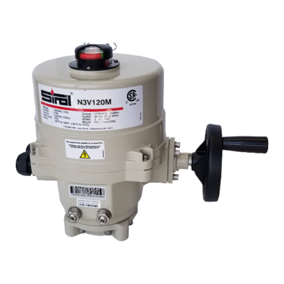
- Page 21 Worm Override Shaft NEMA 4X Sealed Conduit entry (2) - 3/4” External Mechanical Stop Adjustments Collapsible Manual Override Handwheel Main Shaft Ball Bearing Changeable ISO5211 Mounting System ISO5211 Double Square Female drive socket Page 22 of 25 Page 20 of 23 www.siral.us...
- Page 22 Travel cams not Reset end-of-travel cams as detailed on pages 9~11 positioned correctly IOM16 N2, N5 www.siral.us 070716 Page 21 of 23...
- Page 23 Reset end-of-travel cams as detailed on pages 9~11 Travel cams not positioned correctly IOM16 N2, N5 www.siral.us 070716 Page 22 of 23...
- Page 24 This page intentionally left blank www.siral.us IOM16 N2, N5 070716 Page 23 of 23...
Need help?
Do you have a question about the N2 Series and is the answer not in the manual?
Questions and answers