Table of Contents
Advertisement
Quick Links
Advertisement
Table of Contents

Summary of Contents for Canberra iMatic Automatic LB
- Page 1 iMatic™ Automatic LB System User’s Manual 9239221K V1.26...
- Page 2 Copyright 2017, Mirion Technologies (Canberra), Inc . All rights reserved. The material in this document, including all information, pictures, graphics and text, is the property of Mirion Technologies (Canberra), Inc. and is protected by U.S. copyright laws and international copyright conventions.
-
Page 3: Table Of Contents
Table of Contents 1. Introduction ..................1 About this Manual .......................... 1 Typographic Conventions....................... 2 2. Getting Started ................3 Turning on the iMatic ........................3 Power ON Options ........................3 Demo/Troubleshooting Mode......................4 Front Panel Controls ........................6 Power and Battery Indicators ..................... 7 Display ............................ - Page 4 Group Iterations ........................29 System Information ........................30 Unit ID ............................. 30 Unit Serial Number ........................31 Display All Unique IDs ......................31 Display MAC Address ......................32 View DAQ BD Parameters ...................... 33 Version Information ......................... 33 Setup Printer ..........................34 Character/Line ..........................
- Page 5 Define Calibrations ........................55 Edit Cal Name .......................... 57 Bkg Cal Parameters ........................58 α Eff Cal Parameters ........................ 59 β Eff Cal Parameters ........................ 60 Auto Cal Sequence Start ......................60 Define QC Procedures ........................61 Select QC Reference ........................ 62 Daily Bkg Parameters ......................
- Page 6 C. System QC Charts ............... 91 QC Chart Reference........................91 QC Warnings ..........................91 QC Lockout ..........................92 D. Optimizing the CANBERRA iSERIES for Air Sample Counting 93 iSERIES Algorithm ........................93 Testing the Algorithm ......................94 Potential Problems ........................94 Firmware Versions ........................
- Page 7 Installing the Sample Mast ..................... 124 Installing the Lead Shield....................... 124 Installing the Detector ......................129 Installing the Cabinets ......................133 Installing the Monitor Support Arm ..................134 Installing the Batteries......................136 Installing the Printer Shelf ..................... 137 Connecting the System ....................... 138 AC Voltage ..........................
- Page 8 Mechanical Safety: Caution – risk of injury due to moving parts. Personal Safety: Protective gear is required. Environmental Safety: Caution surfaces hot/cold. Manufacturer's Address Mirion Technologies (Canberra), Inc. 800 Research Parkway Meriden, CT. 06450 iMatic Automatic Counting System User's Manual - 9239221K...
-
Page 9: Introduction
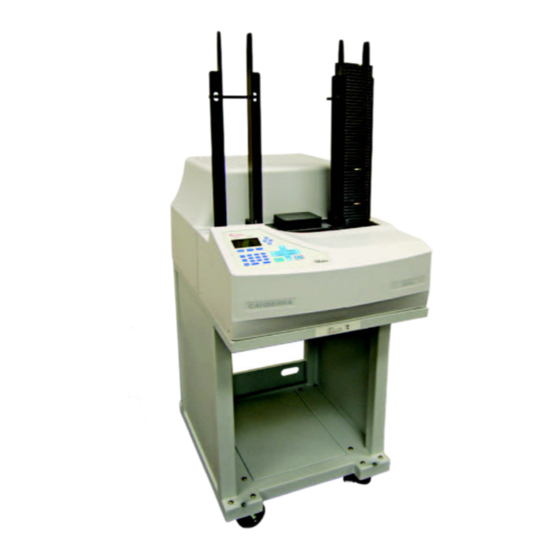
It is this interference that must be determined and corrected for. The Canberra iMatic instrument is an automated single-detector counting system for the measurement of low-level alpha and beta radiation. The system utilizes a series of algorithms to... -
Page 10: Typographic Conventions
Chapter 1 Introduction Typographic Conventions Names of Keys on the Keyboard The names of keyboard keys as they usually appear on the keyboard and are seen in small capital letters (for example, ENTER or ESCAPE). User Entries Text you are expected to type in is shown in Courier New (monospaced style) type. -
Page 11: Getting Started
Turning on the iMatic 2. Getting Started This chapter covers how to turn on the iMatic as well as a brief overview of the front and rear panel controls, and the function of the automated sample changer. Turning on the iMatic The iMatic’s power switch (1/0) controls power to the instrument. -
Page 12: Demo/Troubleshooting Mode
Chapter 2 Getting Started System Master Clear This selection clears or resets all of the items as described in the system reset, and the following parameters: Detector gain is cleared requiring the detector auto gain procedure to be run before any data may be taken. - Page 13 Demo/Troubleshooting Mode β Efficiency Calibrations and β Daily Efficiency QC Checks When in the demo mode and performing a β Efficiency Calibration or β Daily Efficiency QC Check, the pulser produces a spectrum with a statistical distribution similar to that of an actual Sr/ Y efficiency measurement and a counting rate of 25% of the decay-corrected rate of the selected calibration source.
-
Page 14: Front Panel Controls
Chapter 2 Getting Started Procedure I Procedure I produces a spectrum consisting of AmCm with a typical counting rate of 1000 cpm mixed a Radon/Thoron background with a typical counting rate of 1000 cpm. Procedure J Procedure J produces a Radon/Thoron background spectrum with a typical counting rate of 1000 cpm. -
Page 15: Power And Battery Indicators
Front Panel Controls When you first turn on the unit the iMatic’s home screen is displayed: 19Jan2005 09:50:32 Press <Setup> Press <Count> to Begin Automatic Operation Power and Battery Indicators The Power and Battery LEDs are used to indicate the power source and battery status. When batteries are present, the LCD Battery Indicator shows the charge state of the batteries. -
Page 16: Display
Chapter 2 Getting Started LCD Battery Indicator The LCD Battery indicator shows the state of the charged battery from having a low charge to being fully charged as shown in Figure 3. Figure 3 Battery Indicator The batteries are not fully charged until the battery indicator stops flashing. Full charge takes about 12 hours and typical battery life is 6 to 8 hours. -
Page 17: Arrow Keys
Front Panel Controls Arrow Keys The arrow keys are located to the right of the LCD display. The arrow keys provide a means to navigate through the menu system. These keys also allow selection of display information during a sample count and alphanumeric characters. Selecting Alphanumeric Characters During the operation of the iMatic, there are locations where alphanumeric characters can be entered. - Page 18 Chapter 2 Getting Started Table 1 Alphanumeric Characters α δ β Σ iMatic Automatic Counting System User's Manual - 9239221K...
-
Page 19: Numeric Keypad
Front Panel Controls Numeric Keypad An 11-key numeric keypad is used to provide data entry. Enter, Cancel, and Setup Keys Special function keys to confirm data entry and to cancel an operation are provided. A special key that allows you to enter the System Setup is located on the front control panel. -
Page 20: Count Key (Count/Pause/Resume)
Chapter 2 Getting Started Next The Next key advances the sample changer to the next sample. The Next key is disabled during counting or system setup. Previous The Previous key reverses the sample changer to the previous sample. The Previous key is disabled during counting or system setup. -
Page 21: Rear Panel Controls And Connectors
Mirion Technologies (Canberra) may cause an explosion or other fire hazard resulting in personal injury. Mirion Technologies (Canberra) is not liable for personal injury or damage resulting from the use of incompatible batteries. -
Page 22: Sample Changer
Chapter 2 Getting Started USB Type B This is the connection for the USB cable for use with iLink. USB Type A Future product enhancement. Printer This connector is used to attach the iMatic to a printer. The standard printer ®... -
Page 23: Loading Sample Carriers
Sample Changer Loading Sample Carriers The sample changer will only work if it has at least five sample carriers in the system. The first and last carriers must be SAFETY plates as shown in Figure 5. Figure 5 Loading Sample Carriers To load the sample carriers: 1. -
Page 24: Uninterruptible Power Supply
Chapter 2 Getting Started 8. Place an END plate on top of the last User Carrier. 9. Place a SAFETY plate on top of the END plate. Uninterruptible Power Supply The iMatic system contains an internal Uninterruptible Power Supply (UPS) that will power the system for typically 6 to 8 hours when the normal AC mains supply is lost. -
Page 25: Setup Menu
Uninterruptible Power Supply 3. Setup Menu The Setup menu provides logical access to most parameters and features of the iMatic system. Menu choices can be selected two ways. Use the arrow keys to the right of the display to move the selection cursor “>” to desired the item or enter the number (1 through 18) of the desired item. -
Page 26: Delete Data
Chapter 3 Setup Menu Delete Data Sample data is stored in battery-backed memory in the iMatic. A total of 500 records are available to store data. Keep in mind that for each batch counted, an additional record is used for the “Group Done” indicator. In order to prevent sample data from being inadvertently over-written, if the device detects that the selected procedure’s iteration will exceed the 500 record limit, the iMatic will halt operation and display an “Insufficient Memory”... - Page 27 Set Security Level Security OFF Setup Only: Access to the Setup menu is limited to the Supervisor. Users can operate the system without selecting User Name or User Passkey. Setup+User: Access to the Setup menu is limited to the Supervisor. User Name required for all other functions.
-
Page 28: Define Procedure
Chapter 3 Setup Menu If desired, the “Supervisor” User Name may be edited by using the up/down arrow keys or the numeric keypad to edit the letter and the left/right arrow keys to move to the next or previous letter. This ID may be up to 12 characters and/or numbers. Press Enter when finished. -
Page 29: Procedure Name
Define Procedure Move the ">" cursor to the procedure to be edited and then press Enter. If you are starting from the default settings, the display will show: > A Procedure A Define Procedure A > 1 Procedure Name 2 Select Calibration 3 Unk Sample Diameter 4 Select Report 5 Count Time... -
Page 30: Select Calibration
Chapter 3 Setup Menu 5. Modify the Procedure Name. 6. Press the Enter key to accept and automatically advance to the next question in the procedure definition. Press the Cancel key to return to the Define Procedure Menu. Pressing the Cancel key again will bring up a “Save Changes?”... -
Page 31: Select Report
Define Procedure 4. Using the arrow keys, position the cursor “>” to item “3”, Unk Sample Diameter, and then press the Enter key. 5. Enter the active diameter of the user sample in millimeters. 6. Press the Enter key to accept and automatically advance to the next parameter in the procedure. -
Page 32: Count Time
Chapter 3 Setup Menu Count Time The Count Time menu item allows you to enter the time in minutes that a sample is counted from 0.01 to 9,999.99 minutes. The default value is 10.00 minutes. To enter the Count Time: 1. -
Page 33: Count Presets
Define Procedure 6. Press the Enter key to accept and automatically advance to the next parameter in the procedure. Press the Cancel key to return to the Define Procedure Menu. Pressing the Cancel key again will bring up a “Save Changes?” question. -
Page 34: Activity Units
Chapter 3 Setup Menu Activity Units The conversion factor converts sample alpha and beta counts into a desired unit of measure. This is often used for converting the sample counts to a unit of activity other than DPM. The resulting sample net activity will be multiplied by the selected factor. The table below shows for each unit a description of that unit and its conversion factor. -
Page 35: Action Limits
Define Procedure If you choose to use user-defined conversion factor (K User Defined): 1. Select User Defined Unit. 2. Enter the custom conversion factor value from 0.00 to 1.00 x 10 3. Enter the custom conversion factor sigma from 0.00 to 1.00 x 10 4. -
Page 36: Method Blank Enable
Chapter 3 Setup Menu 5. Enter the desired Alpha Warning Limit and then press the Enter key. 6. Enter the desired Alpha Alarm Limit and then press the Enter key. 7. Enter the desired Beta Warning Limit and then press the Enter key. 8. -
Page 37: Group Iterations
Define Procedure 13Jul2005 07:19:46 Procedure A 000:000 1.00 min α: 0 cpm β: 0 cpm Method Blank The activity calculations will still use the efficiencies stored in the calibration associated with the procedure. All printed reports for this procedure will reflect the use of the method blank. -
Page 38: System Information
Chapter 3 Setup Menu System Information The system information menu is used to set system identification information. 4 System Information > 1 Unit ID 2 Unit Serial Number 3 Display All Unique IDs 4 Display MAC Address 5 View DAQ BD Parameters 6 Version Information Unit ID The Unit ID menu item allows you to enter the instruments identification up to 22... -
Page 39: Unit Serial Number
System Information Unit Serial Number The Unit Serial Number menu item allows you to enter the instrument serial number up to 22 alphanumeric characters. To enter a Unit Serial Number: 1. Press the Setup key. 2. Using the arrow keys, position the cursor “>” to item “4” in the menu, System Information, and then press the Enter key. -
Page 40: Display Mac Address
Chapter 3 Setup Menu Procedure: Calibrate: Source: Sample: Report: Smple Det: Guard Det: Batch ID: 5. These are read only fields. Pressing the Enter key will automatically advance to the next item in the System Information list. Pressing Cancel will return to the System Information menu. -
Page 41: View Daq Bd Parameters
System Information View DAQ BD Parameters The View DAQ BD Parameters menu items allows you to view critical operating parameters. To view DAQ board parameters: 1. Press the Setup key. 2. Using the arrow keys, position the cursor “>” to item “4” in the menu, System Information, and then press the Enter key. -
Page 42: Setup Printer
Chapter 3 Setup Menu Setup Printer The Setup Printer menu allows you to define page and print characteristic details specific to each printer. In addition, a timeout function is provided for the parallel printer port so that if an external device is not responding, the iMatic system will continue to count and store data. -
Page 43: Left Margin
Setup Printer Left Margin The Left Margin menu item allows you to set the number of characters from the left printer margin before printing starts. You can enter from zero to the number of characters per line (see previous section); default value is 0. To set the Left Margin: 1. -
Page 44: Top Margin
Chapter 3 Setup Menu Top Margin The Top Margin menu item allows you to set the number of blank lines at top of report page before printing starts. You can enter from zero to the number of lines per page (see lines/page section);... -
Page 45: Lpt Timeout
Define Report LPT Timeout The LPT Timeout menu item allows you to set the time the system waits for a printer response before indicating an error. You can enter from a value 0 to 30 seconds; default is 10 seconds. To set the LPT Timeout: 1. - Page 46 Chapter 3 Setup Menu Complete List of Report Field Selections Channel Attributes Description Sample Sample Num:Itr Sample number (incremental in a batch) : sample iteration Sample ID Alphanumeric Sample ID Date Count date Start time Time of day the sample was started End time Time of day the sample was finished Time...
- Page 47 Define Report Gross Counts Alpha gross counts (3 to 5.6 MeV region), no background subtraction Net Counts Alpha gross counts (3 to 5.6 MeV region) with background subtracted Alpha counts per minute (3 to 5.6 MeV region), no background subtraction Net CPM Alpha counts per minute (3 to 5.6 MeV region) with background subtracted...
- Page 48 Chapter 3 Setup Menu Beta Comp Procedure Activity Radon compensated beta activity is printed in the unit (dpm, Bq, µCi, nCi, pCi or user defined K) selected in the procedure used to perform the analysis. Total uncertainty associated with above Radon compensated Activity X±...
-
Page 49: Edit Title
Define Report Edit Title The Edit Title menu item allows you to edit the title printed at the top of a report. You can enter up to 22 alphanumeric characters. To edit the report title: 1. Press the Setup key. 2. -
Page 50: Clear Last
Chapter 3 Setup Menu 5. Using the arrow keys position the cursor “>” to select the data field to define then press the Enter key. If the field has been previously defined, you may modify the existing data field by selecting another field in its place. 6. -
Page 51: Print
Define Report Print The Print menu item is used for testing report formats. To print a report: 1. Press the Setup key. 2. Using the arrow keys, position the cursor “>” to item “6” in the menu, Define Report, and then press the Enter key. 3. -
Page 52: Print Header
Chapter 3 Setup Menu 7. Press the Cancel key to return to the Select Report menu. Print Header The Print Header menu item allows you to choose to enable or disable printing the report header. The title lines (the top three lines) will always be printed. The calibration and procedure counting information in the header may be suppressed using this menu option. -
Page 53: Select User Source
Define Std Source Select User Source The Select User Source function allows you to edit or define any of the twenty-six available calibration sources stored by the iMatic. The labels and values entered in the standards library are used for reports and efficiency calculations. Note: A BkgBlank, background blank, must be entered in order to perform background calibrations. -
Page 54: Half-Life (Days)
Chapter 3 Setup Menu Radionuclide Template List Cl-36 Co-60 4. To modify the standard name, use the up/down arrow keys to select characters, and the right/left arrow keys to select the character position. Press the Enter key to save the name and advance to the next question. 5. -
Page 55: Source Calibration Month
Define Std Source Source Calibration Month To enter the month of calibration: 1. Press the Setup key. 2. Using the arrow keys, position the cursor “>” to item “7” in the menu, Define Std Sources, and then press the Enter key. 3. -
Page 56: Source Calibration Year
Chapter 3 Setup Menu Source Calibration Year To enter the calibration year: 1. Press the Setup key. 2. Using the arrow keys, position the cursor “>” to item “7” in the menu, Define Std Sources, and then press the Enter key. 3. -
Page 57: Source Calibration Minute
Define Std Source Source Calibration Minute To enter the calibration minute value: 1. Press the Setup key. 2. Using the arrow keys, position the cursor “>” to item “7” in the menu, Define Std Sources, and then press the Enter key. 3. -
Page 58: Detector Parameters
Chapter 3 Setup Menu Detector Parameters The detector parameters menu is provided to enter or edit sample detector and guard detector operational parameters. Note: The detector high voltage and threshold values used to test this system will be set at the factory and should not require editing. Additionally, the sample detector gain will also be set at the factory. -
Page 59: Guard Det Threshold
Detector Parameters 6. Pressing Enter will invalidate all current system calibration procedures. It will also automatically advance to the next question. Pressing Cancel to the warning will return to the Detector Parameters menu. 7. If you desire to only modify the Guard Det HV, pressing the Cancel key will return to the Detector Parameters Menu. -
Page 60: Guard Det Serial Number
Chapter 3 Setup Menu Guard Det Serial Number Guard Det Serial Number menu item allows you to enter the guard detector’s serial number. To enter a guard detector serial number: 1. Press the Setup key. 2. Using the arrow keys, position the cursor “>” to item “8” in the menu, Detector Parameters, and then press the Enter key. -
Page 61: Sample Det Threshold
Detector Parameters WARNING! Continuing will require new gain calibration. Press Enter to continue. Pressing Enter will require a gain calibration be executed before any other type of count is performed. It will also automatically advance to the next question. Pressing Cancel to the warning will return to the Detector Parameters menu. -
Page 62: Sample Det Serial Number
Am peak into a specific reference channel. Note: Canberra offers an Am standard (Model AM50MM) that is specific to this automatic sample detector gain adjustment. If an alternate source is to be used, the face of that source must be precisely 4 mm from the face of the iMatic PIPS detector. -
Page 63: Define Calibrations
Define Calibrations 4. The system will prompt for the Gain Calibration Standard to be selected. Using the down arrow, select the Am source to be used for this calibration and press the Enter button. 5. Enter the number corresponding to the source carrier in the sample changer, which contains the gain calibration standard. - Page 64 Chapter 3 Setup Menu Data Is Stored That Uses Calibration Name Transfer or Delete Data Before Modifying This Calibration Press Any Key You must delete those data records (using SETUP → Delete Data) or transfer them to iLink™ (which deletes data records from iMatic automatically) before the calibration may be modified.
-
Page 65: Edit Cal Name
Define Calibrations 9 Define Calibrations Select Calibration > 1 Calibration 1 Define Calibration 1 1 Edit Cal Name 2 Bkg Cal Parameters 3 α Eff Cal Parameters 4 β Eff Cal Parameters 5 Auto Cal Sequence Start Calibration 2 Calibration 3 Calibration 4 Calibration 5 Calibration 6... -
Page 66: Bkg Cal Parameters
Chapter 3 Setup Menu 5. Modify the Calibration Name. Suggestion: Create a name that details the calibration procedure. For example: 50mm,10min for a procedure that references 50 mm diameter sources and is used to count 50 mm diameter filters for 10 minutes. 6. -
Page 67: Eff Cal Parameters
Define Calibrations 9. Enter the carrier number of the source blank to be used to count the background and automatically advance to the next question in the Define Calibration Parameters definition. α Eff Cal Parameters The α Eff Cal Parameters menu item allows you to define the α efficiency measurement procedure. -
Page 68: Eff Cal Parameters
Chapter 3 Setup Menu β Eff Cal Parameters The β Eff Cal Parameters menu item allows you to define the β efficiency measurement procedure. To edit the β efficiency measurement procedure: 1. Press the Setup key. 2. Using the arrow keys, position the cursor “>” to item “9” in the menu, Define Calibrations, and then press the Enter key. -
Page 69: Define Qc Procedures
Define QC Procedures To edit the Auto Cal Sequence Start: 1. Press the Setup key. 2. Using the arrow keys, position the cursor “>” to item “9” in the menu, Define Calibrations, and then press the Enter key. 3. Using the arrow keys, select the calibration (1 through 10), and then press the Enter key. -
Page 70: Select Qc Reference
Chapter 3 Setup Menu Select QC Reference The Select QC Reference menu item allows you to select the Calibration (see Define Calibrations on page 55) used as the reference for the QC procedure. To select the QC reference: 1. Press the Setup key. 2. -
Page 71: Daily Α Eff Parameters
Define QC Procedures 8. Select the daily background lockout level. Default value is 0 (off). Press the Enter key to accept and automatically advance to the next question in the Daily Bkg Parameters definition. 9. Enter the carrier number of the source blank to be used to count the daily background and automatically advance to the next question in the Define QC Procedures definition. -
Page 72: Daily Β Eff Parameters
Chapter 3 Setup Menu Daily β Eff Parameters The Daily β Eff Parameters menu item allows you to define the daily β efficiency measurement procedure. To edit the daily β efficiency measurement procedure: 1. Press the Setup key. 2. Using the arrow keys, position the cursor “>” to item “10” in the menu, Quality Control, and then press the Enter key. -
Page 73: Set Date/Time
Set Date/Time Set Date/Time The Set Date/Time menu allows you to set the system internal clock. The date and time are printed in fields in the headers of all calibration and data reports. The Set Date/Time menu item allows you to set the internal calendar and clock to the correct date and time including the month, day, year, hours, minutes, and seconds. -
Page 74: Set Year
Chapter 3 Setup Menu Set Year To enter the Year: 1. Press the Setup key. 2. Using the arrow keys, position the cursor “>” to item “11” in the menu, Set Date/Time, and then press the Enter key. 3. Using the Enter key, advance to the Enter Yr 1980..2079 prompt. 4. -
Page 75: Set Second
Define Users 4. The Enter Minute menu is displayed. Using the numeric keypad enter the current minute of the hour and then press the Enter key. Pressing the Enter key will automatically advance to the next question. 5. If only the Minute is modified, pressing the Cancel key will return to the Setup Menu. -
Page 76: Auto - Restack
Chapter 3 Setup Menu 5. The “Enter Passkey” screen allows the Supervisor to enter any 7-character combination of alphanumeric text as a passkey for this User. If the selected User Name/Passkey have not been previously edited, the Supervisor’s Passkey will be displayed. The Supervisor’s Passkey may be edited one character at a time or, if the keypad is used to enter any number for the first character, the passkey will clear except for the one entered number. -
Page 77: Clear Qc Log
Clear QC Log 14 Enable Time Count Enable Auto-restack > 1 OFF 2 ON 1. To enable the Timed Count feature press Setup. 2. Using the arrow keys, position the cursor “>” to item “14” and then press the Enter key. 3. -
Page 78: Data Output Setup
Chapter 3 Setup Menu Data Output Setup The Output Setup menu is used to program the output modes and the output configuration of the iMatic. The Output Modes describe the data printing, transfer to iLink, and automatic delete options, while the Output Configurations describe the interfaces available and how they are used. -
Page 79: Output Configuration
Data Output Setup Print Line by Line/Delete - The Report, as selected by the procedure, is automatically printed one line at a time after the completion of each count record. The count data is automatically deleted from the unit’s internal memory after printing. -
Page 80: Printer Enable
Setup Menu item. Access to these items should only be attempted at the direct instruction of Mirion Technologies (Canberra) engineering staff members. If any item is opened and changed and “Yes” is responded when asked to “Save Changes”, an “Enter Security Code”... -
Page 81: Setup Test Pulser
Setup Test Pulser Setup Test Pulser The Test Pulser menu item allows you to select the amplitude (pulse-height) of an internal test pulser for diagnostics purposes. The iMatic pulser generates pulses and injects these pulses at the input of the PIPS detector preamplifier. The amplitude can be set as a percentage of full scale. -
Page 82: Pulser On/Off
Chapter 3 Setup Menu Pulser On/Off The Pulser On/Off menu item allows you to turn the internal pulser on or off. This is done by: 1. Press the Setup key. 2. Using the arrow keys, position the cursor “>” to item “18” in the menu, Setup Test Pulser, and then press the Enter key. -
Page 83: Display Menu
Setup Test Pulser 4. Display Menu Depressing the front panel Display key displays a menu that allows you to set the display contrast and viewing angle for the best visibility. The Display key is only active when the iMatic system is idle. LCD ADJUST Angle: Up/Dn Backlight: Lt/Rt... -
Page 84: View Menu
Chapter 5 View Menu 5. View Menu The function of the front panel View key depends upon the operational state of the iMatic system. While the iMatic is idle, with no count results displayed, the View key allows sample count data or calibration values to be reviewed. VIEW 1 View Sample Data Memory Status 1 of 500 used... - Page 85 Sample Data The system briefly displays a count of the total number of data records stored, and the maximum capacity of the memory. For example: 1 of 51 500 records (max) The system then automatically displays the first data record. Pressing the left or right arrow steps the display forward or backward through the stored data records.
-
Page 86: Calibration Data
Chapter 5 View Menu Raw Spectrum Pressing View again toggles the screen to the raw data spectrum display. The spectral display shows 256 channels of raw counts with the full scale units at the top of the Y axis. While viewing the spectrum, the full scale mode and value may be changed using the up, down, left, and right arrow keys. -
Page 87: Qc Data Display
QC Data Display QC Data Display QC data is now available for display from within the View key menu. To access, from the main screen press View. Select #3 View QC Data. All of the QC data selections are shown in a menu: QC Reports 1 α... -
Page 88: Print Menu
Chapter 6 Print Menu 6. Print Menu The front panel Print key provides access to a print menu where all print functions of the iMatic are available. In many cases a report will automatically be printed when a procedure is run. If an additional report must be printed without recounting samples, and the sample data is still stored in the iMatic, the report can be selected and printed from this menu. -
Page 89: Print All Groups
Print All Groups Print All Groups Every group of samples counted and stored in memory will be printed using the report template selected in the counting procedure used to count each group of samples. 1. Press the Print key. 2. Move the “>” cursor to “2 ALL Grps” and then press Enter. PRINT MENU 1 Most Recent Grp >... -
Page 90: Print System Reports
Chapter 6 Print Menu Select Report 1 SAMPLE ACTIVITY 2 ALPHA COMPENSATED DATA 3 RAW DATA 4 NCPM DATA 10 USER REPORT Printing Report Press Cancel to Terminate PRINTER FAULT 1 Re-try 2 Cancel Print 3 Printer OFF Report Completed Press Cancel B Procedure B C Procedure C... - Page 91 Print System Reports To print a system report: 1. Press the Print key. 2. Move the “>” cursor to “4 System Reports” and then press Enter. 3. Select the desired report and then press Enter. PRINT MENU 1 Most Recent Grp 2 ALL Grps 3 Select Grp/Rpt >...
-
Page 92: Calibrating The System
Appendix A Calibrating the System A. Calibrating the System The iMatic system, like any precision analytical instrument, must be calibrated in order to measure samples with accurate, precise, and reproducible results. The iMatic has features that make calibration easy to set up and repeat. With dedicated calibration procedures, the system can be set up quickly and calibration repeated easily with minimal impact on productivity. -
Page 93: Entering Calibration Source Information
Entering Calibration Source Information For each step of the calibration appropriate parameters are entered from the menu choices. The menu will automatically move to the following step as you select the parameters required for each procedure. Note: The default settings should be fine, at least to get started, for most users. Entering Calibration Source Information Note: A background blank, Americium alpha and Strontium beta standard, will already be defined when the unit is received. -
Page 94: Selecting Output Mode
Appendix A Calibrating the System 10. Using the arrow keys or the numeric keypad, enter the hour of calibration. Press the Enter key to accept and advance to the next question. 11. Using the arrow keys or the numeric keypad, enter the calibration minutes value. - Page 95 Modifying Calibration Procedures 5. Modify the Calibration Name. Press the Enter key to accept and automatically advance to the next question in the calibration definition. 6. Enter the background measurement time in minutes. Press the Enter key to accept and automatically advance to the next question in the calibration definition.
-
Page 96: Measuring Alpha And Beta Backgrounds And Efficiencies
Appendix A Calibrating the System 18. Enter the calibration sequence starting procedure. The system will run each calibration procedure in sequence starting with the procedure specified in this menu. Normally, a calibration will start with a background procedure and then proceed to the efficiency measurements. - Page 97 Measuring Alpha and Beta Backgrounds and Efficiencies 5. After all enabled calibration procedures have been run, the system will display: AUTO CAL OPERATION Complete Press Any Key To View Calibrations The system will show the first completed calibration with the following prompts: Calibration 1 Bkg(cpm)
-
Page 98: Counting Samples
Appendix B Counting Samples B. Counting Samples The primary function of the iMatic is to count user samples and provide accurate alpha and beta results that are Radon and Thoron corrected. In order to count samples accurately and correctly the system must be properly calibrated and procedures must be created that provide the sensitivity requirements of the sample to be analyzed. -
Page 99: System Qc Charts
QC Chart Reference C. System QC Charts The iMatic includes a versatile QC Charting function that allows background and efficiency QC information to be tracked over time. The QC Chart features a 90-point moving-window that allows multiple-points-per-day to be included in the chart. The Printer Setup default is 90 characters per line to allow the time-of-day to be included for each measurement. -
Page 100: Qc Lockout
Appendix C System QC Charts QC Lockout The QC Lockout feature allows the system to apply a simple test to the Daily Background, Alpha Efficiency, and Beta Efficiency to disable (lockout) the system if results exceed acceptance limits. The QC Lockout feature compares the daily measurement to the QC chart reference parameter. -
Page 101: Optimizing The Canberra Iseries For Air Sample Counting
The CANBERRA iSERIES algorithm is discussed in Mirion Technologies (Canberra) literature. An entire algorithm manual is available from Mirion Technologies (Canberra) (part number 9237566). This appendix will not discuss the details of the algorithm in detail beyond what is required to optimize the results. The steps performed by the algorithm are summarized below: 1. -
Page 102: Testing The Algorithm
Appendix D Optimizing the CANBERRA iSERIES for Air Sample Counting Testing the Algorithm The recommended testing method is to use real samples that have been collected in the normal manner. A longitudinal study should be conducted on each sample to determine that the activity value observed prior to the radon and/or thoron decay is statistically equivalent to the results after the radon and/or thoron has decayed. -
Page 103: Gain Calibration
Figure 6 Transuranic Peaks and Radon Progeny Gain Calibration The CANBERRA iSERIES is shipped from the factory with the system gain calibration having been performed. The gain is set at the factory using an Am-241 radioactive standard source physically identical to the AM50MM available from Mirion Technologies (Canberra). - Page 104 Appendix D Optimizing the CANBERRA iSERIES for Air Sample Counting The GAIN Calibration should only be necessary in the event of: • Change of Hardware • System Master Clear with no restorable personality file available • Radon compensation issues not resolved following the recommendations...
-
Page 105: Analysis Calibrations
iSERIES Algorithm When performing a GAIN calibration it is crucial that the active face of the standard is exactly 4 mm from the front of the detector. Most “planchet” type standard sources cannot be placed with the active area in the proper location. When using the SH-CAL holder shown in Figure 9 (iSOLO) or the IS-CAL shown in Figure 10 (iMATIC) the AM50MM standard will be placed exactly the correct distance from the detector. -
Page 106: Sample Distance
Appendix D Optimizing the CANBERRA iSERIES for Air Sample Counting For the most accurate results, users should obtain standard sources that are as much like the sample collection media as possible. If efficiency standard sources that are unlike the samples in physical makeup or contains radioactive isotopes unlike those likely to be found the sample, a systematic bias will be introduced to the results. -
Page 107: Sample Analysis Delay
(Po-218) has energy of 6.0 MeV with half-life of 3.05 minutes. Mirion Technologies (Canberra) recommends aging each sample for 10 minutes prior to the start of the first analysis. Practically speaking, this limitation may only apply if the full alpha (Cm-242, Cm-244) region is being used but the recommendation still holds for the other regions as well. -
Page 108: Sample Collection Time
Appendix D Optimizing the CANBERRA iSERIES for Air Sample Counting Sample Collection Time Air samples are typically collected for as little as a few minutes to as much as several days. As stated earlier in this application note, early versions of the algorithm assumed that the Thoron progeny (ThC and ThC') were present if the Radon progeny (RaC') existed. - Page 109 iSERIES Algorithm Figure 13 24 Hour PTFE Air Filter Tenth Count Figure 14 25 Hour PTFE Sample 300 Minutes after Collection iMatic Automatic Counting System User's Manual - 9239221K...
-
Page 110: Filter Media Selection
Appendix D Optimizing the CANBERRA iSERIES for Air Sample Counting Figure 15 1 Hour PTFE Sample 10 Minutes After Collection Users should be cognizant of the fact that different collection times will yield different responses due to influences. Longer collection times tend to have a higher ratio of thoron progeny to radon progeny until the point at which thoron equilibrium is reached. - Page 111 iSERIES Algorithm Figure 16 One Hour Glass Fiber Filter The activity results show a dramatic difference as well. Table 2 shows the difference in the activity of the compensated results using the two filters. Not only is there a huge difference in the alpha results, but the low tailing of the alpha falling into the beta channel is significant as well.
-
Page 112: Regions
Appendix D Optimizing the CANBERRA iSERIES for Air Sample Counting In reviewing a recent user's actual field results using a glass fiber filter, the algorithm correctly compensated for 95%+ alpha interference and 90%+ beta interference. Regions Another way to improve the compensated results is to use the alpha region most closely resembling nuclides expected to be found in any contaminated sample. -
Page 113: Manual Gain Adjust
iSERIES Algorithm Table 5 Sample Activity Range 1 σ σ % Alpha 3 - 6.4 Range Range High Glass Fiber Model LB5211 A-O 10.59 % PTFE 25.00% Glass Fiber Model LB5211 A-O 14.61% PTFE 50.00% Using a 95% confidence interval (2 standard deviations) we can easily see that the range of Glass Fiber Model LB5211 A-O was from 134 to 206. - Page 114 Appendix D Optimizing the CANBERRA iSERIES for Air Sample Counting Figure 17 Incorrect Results with Improper Gain Cal It sometimes happens that a facility is aware that the gain calibration is set incorrectly for their standards, yet they do not possess a proper Am-241 standard to perform a new gain calibration.
- Page 115 iSERIES Algorithm Step 1 - Determine if 7.68 MeV Peak is in channels 195-196 Collect a sample on a pump with radon present. Count the fresh air sample in the iSOLO or iMATIC for a long enough period so that the peak from the 7.68 MeV Po-214 is clearly seen.
- Page 116 Appendix D Optimizing the CANBERRA iSERIES for Air Sample Counting Figure 22. Figure 20 Save As Dialog for Export The data will need to be imported into Excel. From the “Files of type” list box, select “Text Files” as shown in Figure 21. If prompted, choose delimited as the data type.
- Page 117 iSERIES Algorithm It should create a table that includes 3 rows and 256 columns as shown in Figure 22. Figure 22 Data Imported Into Excel Row 1 - Channel Number Row 2 - Uncompensated Data Row 3 - Compensated Data The peak from the naturally occurring Radon should fall into channels 195-199 which correspond to columns GN-GR.
- Page 118 Appendix D Optimizing the CANBERRA iSERIES for Air Sample Counting Figure 23 Radon Peak in Channel 196 Figure 24 shows the exported data in the Spectral View of Link. Figure 24 Export Radon Data Shown in iLink Step 2 - Create Personality Backup To manually modify the gain, first export the system personality to the XML format as described in the iLINK User's Manual.
- Page 119 iSERIES Algorithm The iSERIES personality is in XML (extended markup language) format that can be edited with a text editor such as note pad. Figure 25 XML Personality File Open Explorer and navigate to the locations where the XML file is located. Right click on the file and choose “Open With"...
-
Page 120: Radon Stripping Verification Tests
Appendix D Optimizing the CANBERRA iSERIES for Air Sample Counting Step 5 – Verify Results Go to step 1 and check if the peak falls into the correct channel range. Repeat steps 3 and 4 until the peak is in the correct location. -
Page 121: Updating Imatic Firmware
Setting Up HyperTerminal E. Updating iMatic Firmware The iMatic Flash Loader Utility is a resident program that resides in the protected boot blocks of the flash memory, and allows the user application program to be loaded into the flash memory using a standard PC based communications program (such as HyperTerminal). - Page 122 Appendix E Updating iMatic Firmware 2. Define an the new connection as “iSeries” as shown in Figure 27. Figure 27 Entering a Connection Name 3. Choose to connect using COM1 (or COM2 as necessary) as shown in Figure Figure 28 Choosing the Communication Port iMatic Automatic Counting System User's Manual - 9239221K...
-
Page 123: Using The Flash Loader Utility
Using the Flash Loader Utility 4. Select the following communication properties as shown in Figure 29: Figure 29 Entering the Communication Properties • 57600 bits per second • 8 data bits • No parity • 2 stop bits • No flow control Using the Flash Loader Utility This section contain the instruction necessary to use the Flash Loader Utility. - Page 124 Appendix E Updating iMatic Firmware 3. While holding down the spacebar on the PC keyboard, apply power to the iSeries instrument. The following message in the HyperTerminal window indicates that the instrument entered the iSeries Flash Loader Utility program and identified the flash memory: 4.
- Page 125 Using the Flash Loader Utility 6. Start the transfer by selecting Transfer | Send File… from the HyperTerminal menu as shown in Figure 30. Figure 30 Transferring Files 7. Select the file to be sent and Xmodem Protocol as shown in Figure 31. Figure 31 Selecting the File to Transfer iMatic Automatic Counting System User's Manual - 9239221K...
- Page 126 Otherwise the Power On Options menu described in Power On Options on page 3 will appear. Contact Canberra as to whether a Master Clear or System Reset is required as part of the firmware upgrade as these options would require redoing calibrations and/or the gain calibration.
-
Page 127: System Installation
Table capable of holding 365 kg (800 lb) or the optional iMatic Mobile Cart Note: The Canberra iMatic Low Background System requires a sturdy 66 cm (26 in.) width by 89 cm (35 in.) depth table that is rated to support a minimum of 365 kg (800 lb). -
Page 128: Site Selection
Failure to provide a suitable table may result in additional service charges in the event that Mirion Technologies (Canberra) On-Site Service is required. WARNING: The low-background system’s mobile cart is designed for limited mobility. -
Page 129: Ac Power Source
Preparation Figure 33 Physical Site Requirements The selected site should offer a typical counting lab environment with controlled temperature and humidity; refer to Specifications starting on page 143. The area should be free of dust and other airborne contaminants (Radon gas, etc.). The site should not expose the system to excessive vibrations from heavy equipment or machinery. -
Page 130: Installation Of Unit
Appendix F System Installation Remove the top and side packing materials from the shipping crates. Place the packing materials in an out-of-the-way location, but do not discard them until after the system is fully assembled and calibrated. Figure 34 Removing the Shipping Bands Installation of Unit Mounting the System Mount the iMatic following the steps below. - Page 131 Installation of Unit securely fastened to the table using eight 5/16 in. grade 8 bolts, as shown in Figure 35, after removing the cabinets in step 2. Carefully remove the larger rear cabinet housing by removing the four 6 - 32 x 1/2 in. socket head cap screws from the back and the two 6 - 32 x 3/8 in.
-
Page 132: Installing The Sample Mast
Appendix F System Installation Installing the Sample Mast Carefully remove the sample mast assemblies from the accessory box. Mount the mast assemblies to the sample changer assembly as shown in Figure 36 using the 8-32 x 3/8 in. socket-head cap screws provided in the accessory hardware box. The left (Receive Stack) and right (Send Stack) mast assemblies are different;... - Page 133 Installation of Unit Note: The lead shield parts are very soft and easily damaged by improper handling. The following precautions should be followed to prevent deforming the lead parts: • Always lift the lead parts from the larger (more substantial) areas, do not use the smaller areas as "handles"...
- Page 134 Appendix F System Installation Step 1 Temporarily loosen the four bolts that hold the sample changer to the base plate and back the bolts out about 1/4 inch. This will allow the sample changer to be moved slightly to facilitate installation of the lead shield parts. Install the Bottom Ring and the four bottom layer Flat Rings of the lead shield onto the Lead Shield Support Plate with the annular projections facing upward and the flat quadrant towards the rear of the instrument.
- Page 135 Installation of Unit Step 2 Tighten the four bolts that hold the sample changer to the base plate. Carefully place the Center Middle lead piece around the sample changer slide. Install the Left and Right Side pieces. Install the Left and Right Rear brick and secure with the Thumb Screws.
- Page 136 Appendix F System Installation Figure 39 Installing the Four Top Layer Lead Shield Rings Step 4 Install the Top Ring and secure the completed assembly using the four 5/8 in. - 11 x 14 in. bolts. Note that the 5/8 in. metal washer goes directly under the head of the bolt and that the 5/8 in.
-
Page 137: Installing The Detector
Installation of Unit Installing the Detector The iMatic PIPS detector normally installed into the PIPS detector mounting assembly at the factory. The detector should not be removed from the mounting assembly needlessly because of the potential to damage the detector and mounting assembly during installation. - Page 138 Appendix F System Installation Step 2 Carefully open the PIPS detector shipping box and remove the detector being careful not to let the detector slide out of the protective cap. Screw the detector onto the detector installation base by rotating the detector clockwise. Set the base/detector assembly on a sturdy flat surface and remove the protective cap from the PIPS detector.
- Page 139 Installation of Unit Figure 43 Using the Detector Installation Tool Step 4 Insert the detector installation tool into the recessed PIPS detector mounting area until the PIPS detector connector is centered on the mating connector of the PIPS Detector Mounting Assembly. Rotate the installation tool clockwise until the detector is firmly seated.
- Page 140 Appendix F System Installation Step 5 Carefully slide the PIPS Detector Mounting Assembly (with PIPS detector installed) onto the rails of the sample changer (Do not use the PMT assembly projecting from the PIPS Detector Mounting Assembly as a handle) and secure with two 6 - 32 x 3/8 in.
-
Page 141: Installing The Cabinets
Installation of Unit Step 7 Connect the wires from the PIPS Detector Mounting Assembly to the DAQ Board Assembly as illustrated. To prevent cables from touching rear cabinet, affix cable mount to lead shield and secure all cables to cable mount with supplied cable tie. Refer to Figure 47. -
Page 142: Installing The Monitor Support Arm
Appendix F System Installation Installing the Monitor Support Arm The monitor support arm should be mounted to the left side of the LB system. Refer to Figure Figure 48 and Figure 49. 1. Mount the interface bracket to the mobile cart using two 3/8 in. - 24 x 4 in. SHCS. - Page 143 Installation of Unit The height of the support arm can be adjusted by loosing the plastic knob. Figure 49 Installing the Monitor Support Arm - Front View iMatic Automatic Counting System User's Manual - 9239221K...
-
Page 144: Installing The Batteries
Appendix F System Installation Installing the Batteries The iMatic rechargeable, NiMH batteries are removed prior to shipment. The following instructions describe how to properly re-install these batteries. Remove both battery access covers by inserting a coin into the slot and rotating counterclockwise 90 degrees while lightly pressing inward. -
Page 145: Installing The Printer Shelf
Installation of Unit Installing the Printer Shelf The optional printer shelf can be mounted to either side of the system. Survey the area where the system will be installed and select the side of the system that will allow room for the printer shelf to extend out when it is in the raised position. -
Page 146: Connecting The System
Appendix F System Installation Connecting the System AC Voltage The iMatic system requires an ac power source of 100-240 Vac at 50-60 Hz. The input voltage is automatically selected by the system power supply. The input power requirements of the printer and any other system accessories should be verified using the manuals provided by the respective manufacturers. -
Page 147: Technical Reference
Cleaning the PIPS Detector G. Technical Reference This Technical Reference includes useful information about the iMatic not covered elsewhere. Cleaning the PIPS Detector This section covers how to properly clean the PIPS® detector. WARNING: You must never use Acetone to clean the PIPS detector. -
Page 148: Battery Care
Memory Backup Battery Internal battery for memory and real time clock. Note: The typical battery life is 5 years. Please contact Mirion Technologies (Canberra) if you experience a problem with the batteries. iMatic Automatic Counting System User's Manual - 9239221K... -
Page 149: Protected Memory Corruption
Protected Memory Corruption Protected Memory Corruption The iMatic tests the status of the protected memory each time power is applied to the unit. If the “memory status word” indicates that the memory is corrupted, the unit automatically re-initializes the detector parameters, system unique identifiers and the real-time clock to default values. -
Page 150: Ilink
Appendix G Technical Reference iLink The iMatic will interface via RS-232 to a PC running iLink. An RS-232 communications cable was supplied with the iMatic for this interface. Connect this cable from the rear panel RS-232 connector to the PC. In order for iLink to retrieve or download configuration information from or to the iMatic, the system must first be at the home or idle screen. -
Page 151: Specifications
Notes: For complete list of accessories, please refer to the iMatic Automatic Alpha/Beta Counting System Super Spec Sheet. Performance specifications are guaranteed at the Mirion Technologies (Canberra) manufacturing facility. Performance BACKGROUND – Sample detector threshold set at 125 keV and guard detector discriminator set at 10%. -
Page 152: Physical
Appendix H Specifications Physical DISPLAY – 160 x 80 pixel LCD graphic display with LED backlight (67.2 x 33.6 mm high viewing area with 0.39 x 0.39 mm pixel size). COMPATIBLE FILTER SIZES – Loose filters 25 mm to maximum 60 mm diameter. Optional holders for NFS/RPS, PAS, and SAS card mounted filters. -
Page 153: Rear Panel Connections
Rear Panel Connections Rear Panel Connections Power – 9 to 15 V, 5 A max. 10/100 Ethernet – Future option. USB Peripheral – Full Speed USB interface for host communication; rear panel USB Series B connector. USB Host – Future option. Printer –... -
Page 154: Installation Considerations
139 there are no internal adjustments or maintenance required. Operating Protection Impairment Mirion Technologies (Canberra) is not liable for any operational malfunctions or personal injuries due to mishandling or unauthorized repair and maintenance not detailed in this manual. -
Page 155: Fcc Notice
J. FCC Notice The following paragraphs are notices required by Federal Communications Commission (FCC) rules, Part 15, Subpart A. “The user is cautioned that any changes or modifications not expressly approved by the party responsible for compliance could void the user’s authority to operate the equipment.”... - Page 156 Notes iMatic Automatic Counting System User's Manual - 9239221K...
-
Page 157: Index
Index Changing analysis parameters ......... 72 About this manual .......... 1 NiMH batteries........136 Action limits ..........27 PIPS detector ......... 129 Activity Units ..........26 the output mode........70 pre-defined ..........26 Charge status of battery ........8 user-defined ..........27 Charging the batteries ........ - Page 158 calibration procedure ....... 55 calibration source ........44 Measuring alpha/beta backgrounds ....88 counting procedure ........20 Measuring alpha/beta efficiencies ....88 method blank ........... 28 Memory report's title..........41 backup battery ........140 Entering corruption ..........141 alphanumeric characters ......9 Method blank, enabling ........
- Page 159 printing the report 's header ..... 44 System calibration ........84 Returning to the previous menu ....11 System date/time .......... 65 RS-232 connector ......... 14 Turning on/off the iMatic ....... 3 Sample changer ..........14 advancing to next group ......12 advancing to next sample ......
- Page 160 Notes iMatic Automatic Counting System User's Manual - 9239221K...
- Page 161 ____________________________________________________ Warranty Mirion Technologies (Canberra) Inc. (we, us, our) warrants to the customer (you, your) that for a period of ninety (90) days from the date of shipment, software provided by us in connection with equipment manufactured by us shall operate in accordance with applicable specifications when used with equipment manufactured by us and that the media on which the software is provided shall be free from defects.
Need help?
Do you have a question about the iMatic Automatic LB and is the answer not in the manual?
Questions and answers