SERVICE
DISHWASHER
DISHWASHER
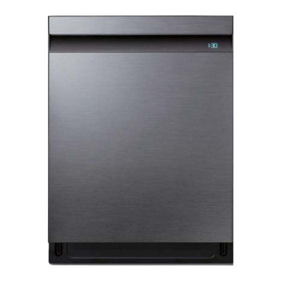
Model Name : DW80R9*** Series
Model Code : DW80R9950UG/AA
DW80R9950US/AA
DW80R9950UG/AC
DW80R9950US/AC
Manual
1. Safety Instructions
2.
3. Disassembly and Reassembly
4. Troubleshooting
5. PCB Diagram
6. Wiring Diagram
7. Reference
CONTENTS


Need help?
Do you have a question about the DW80R9 Series and is the answer not in the manual?
Questions and answers