Table of Contents
Advertisement
SERVICE
WASHING MACHINE (TOP-LOADING)
WASHING MACHINE
TOP-LOADING TYPE
Basic Name : WA7750M
Basic Code :
WA52M7750AW/A4
Model Name : WA50R5400AV
(WA7000R)
Model Code : WA50R5400A*
WA50R5200A*
WA54R7600A*
WA54R7200A*
WA50T5300A*
Manual
1. Safety Instructions
2. Features and Specifications
3. Disassembly and Reassembly
4. Troubleshooting
5. PCB Diagram
6. Wiring Diagram
7. Reference
CONTENTS
Advertisement
Table of Contents

Related Manuals for Samsung WA7750M


Summary of Contents for Samsung WA7750M
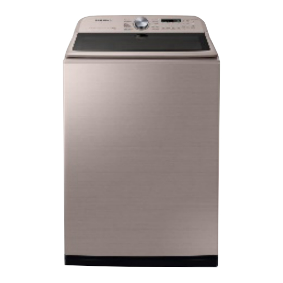
- Page 1 WASHING MACHINE TOP-LOADING TYPE Basic Name : WA7750M Basic Code : WA52M7750AW/A4 Model Name : WA50R5400AV (WA7000R) Model Code : WA50R5400A* WA50R5200A* WA54R7600A* WA54R7200A* WA50T5300A* SERVICE Manual WASHING MACHINE (TOP-LOADING) CONTENTS 1. Safety Instructions 2. Features and Specifications 3. Disassembly and Reassembly 4. Troubleshooting 5.
-
Page 2: Table Of Contents
CONTENTS 1. Safety instructions ..............1 1-1. -
Page 3: Safety Instructions
1. SAFETY INSTRUCTIONS 1-1. SAFETY INSTRUCTIONS FOR SERVICE ENGINEERS ► Be sure to observe the following instructions to operate the product correctly and safely to prevent possible accidents and hazards while servicing. ► Two types of safety symbols, Warning and Caution, are used in the safety instructions. Hazards or unsafe practices that may result in severe personal injury or death. WARNING Hazards or unsafe practices that may result in minor personal injury or property damage. CAUTION WARNING BEFORE SERVICING... - Page 4 WARNING WHILE SERVICING • Check if the power plug and outlet are damaged, flattened, cut or otherwise degraded. 4 If faulty, replace it immediately. Failing to do so may result in electric shock or fire. 4 If plug is faulty replace it, if outlet in consumers home is faulty have consumer call an electrician to replace. • Completely remove any dust or foreign material from the housing, wiring and connection parts. 4 This will prevent a risk of fire due to tracking and electrical hazard. • When connecting wires, make sure to connect them using the relevant connectors and check that they are connected properly. 4 If tape is used instead of the connectors, it may cause fire due to tracking. • Make sure to discharge the PBA power terminals before starting the service. 4 Failing to do so may result in a high voltage electric shock. • When replacing the heater, make sure to fasten the nut after verification that it is inserted into the bracket-heater. 4 If not inserted into the bracket-heater, it touches the drum and could cause noise and electric leakage. WARNING AFTER SERVICING • Check the wiring. 4 Ensure that no part of the wiring harness makes contact with any rotating part or sharp edges. • Check for any water leakage. 4 Perform a test run for the washing machine to ensure no leakage under the machine , at any hose connection, or at the drain hose. • Do not allow consumers to repair or service any part of the washing machine themselves.
- Page 5 CAUTION BEFORE SERVICING • Do not sprinkle water onto the washing machine directly when cleaning it. 4 This may result in electric shock or fire, and may shorten the product’s life cycle. • Do not place any containers with water on the washing machine. 4 If the water is spilled, it may result in electric shock or fire. This will also shorten the product’s life cycle. • Do not install the washing machine in a location exposed to snow or rain. 4 This may result in electric shock or fire, and shorten the product’s life cycle. • Do not press a control button using a sharp tool or object. 4 This may result in electric shock or damage to the product. CAUTION WHILE SERVICING • When wiring a harness, make sure to seal it completely so no liquid can enter. 4 Make sure that they do not break when force is applied. • Check if there is any residue that indicates liquid entered the electric parts or harnesses. 4 If any liquid has entered into a part, replace it or ensure no remaining moisture inside the part. • If you need to place the washing machine on its back or side for servicing purposes, place a support(s) on the floor and lay it down carefully so its back/side is on the floor. 4 Do not lay it down on its front. This may result in cosmetic damage to frame front and/or damage to the tub. Safety Instructions _ 3...
- Page 6 CAUTION AFTER SERVICING • Check the assembled status of the parts. 4 Now is a good time to inspect your work. Review all connections and wiring, including mounting hardware. • Check the insulation resistance. 4 Disconnect the power cord from the power outlet and measure the insulation resistance between the power plug and the grounding wire of the washing machine. The value must be greater than 10MΩ when measured with a 500V DC Megger. • Ensure washing machine is level by pressing down on corners to check for any movement. If not level, adjust legs and check again until no movement is present. Verification that unit is level will reduce customer dissatisfaction and redo call. 4 Vibrations can shorten the lifetime of the product. 4 _ Safety Instructions...
-
Page 7: Features And Specifications
2. FEATURES AND SPECIFICATIONS 2-1. FEATURES Features Description • A large 5.4/5.0cu.ft capacity means you can quickly wash more laundry in Large Capacity a single load, saving you time and effort, without the burden of frequent washes. • Cut your laundry time by up to 40% and clean better. Simply select Super Speed to wash a full load in just 36 minutes. -
Page 8: Specifications
2-2. SPECIFICATIONS TOP LOADING WASHER TYPE WA54R7600A* WA54R7200A* WA50R5400A* WA50R5200A* WA50T5300A* A. Height 44.6” / 1132mm B. Width 27.5”/699mm DIMENSION (Inches / cm) C. Height with Door open 58.3” / 1480mm D. Depth 29.4” / 747mm WATER PRESSURE 20~116psi (137~800kPa) WEIGHT 61kg (134lb) 60kg (132lb) -
Page 9: Detail Features
2-3. DETAIL FEATURES Grade WA54R7600A* WA54R7200A* WA50R5400A* WA50T5300A* Image Capacity (cu.ft/DOE) Smart Care Super Speed Self Clean Active WaterJet Swirl+Drum Features Washing Cycles Internal Heater VRT PLUS Pulsator material Max rpm Motor F-DDM F-DDM F-DDM F-DDM Color Black White Black White Black White Champagne Main display... - Page 10 Grade WA50R5200A* WA52M7750A* Image Capacity (cu.ft/DOE) Smart Care Super Speed Self Clean Active WaterJet Swirl+Drum Features Washing Cycles Internal Heater VRT PLUS Pulsator material Max rpm Motor F-DDM Color White White Inox Main display 18:88 18:88 Jog Dial Chrome Chrome Design Led color Ice-blue...
-
Page 11: Options Specifications
2-4. OPTIONS SPECIFICATIONS Item Item Name Code No. Remark HOSE-HANGER DC61-00224B Default DC68-04037A (Model No : WA50R54*) MANUAL-BOOK Default DC68-04037C (Model No : WA50R52*) CABLE TIE 6501-000121 Default ASSY CAP V.W DC97-18313A Default LEG RING DC61-03458A 5.4cu.ft Only Note • Customer can purchase Water supply, drain hoses and assy leg support from a service center. -
Page 12: Disassembly And Reassembly
3. DISASSEMBLY AND REASSEMBLY 3-1. TOOLS FOR DISASSEMBLY AND REASSEMBLY Tool Type Remarks 10mm Pulsator(1), Assy stator(5), Support saddle(4), Box driver Assy clutch(11), Assy rotor(1) 17mm 10mm Double-ended Replaced by box driver spanner 17mm A Tool for protecting empty turning of bolt or abrasion from using box driver Vice pliers For disassembly of Spin drum... -
Page 13: Standard Disassembly Drawings
3-2. STANDARD DISASSEMBLY DRAWINGS ► This is a standard disassembly diagram and may differ from the actual product. Use this material as a reference when disassembling and reassembling the product. Part Figure Description 1. Remove the 5 screws holding the control panel assembly. 2. Separate the assy panel upward with the door slightly open. 3. Separate the hass wire from cover connector and wires connected to the sub PCB. Sub and Main PCB Assembly 4. Pull the knob encoder to separate it and then remove the 2 fixing screws. - Page 14 Part Figure Description 1. After separating the control panel, separate the water valve housing. 2. Remove the 3 fixing screws. Water Valve 3. Remove the wire-harness and release the clamp connecting the hose. When releasing the clamps, take care that you do not tear the hoses. 1. After separating the control panel, remove 4 fixing screws holding the door lid T.C. Door Assembly 2. Separate the door. 12 _ Disassembly and Reassembly...
- Page 15 Part Figure Description 1. Remove the 2 Screws. 2. Separate the control Panel assemble. 3. Remove the 4 Screws. Top Cover Assembly & Door Switch Common (continued) 4. Separate the Back Cover. 5. Separate the Pump Wire from the wire holders (2 Points). Disassembly and Reassembly _ 13...
- Page 16 Part Figure Description 6. Separate the Pump Wire Connector (2Points). Pump Wire may snap if you separate top Top Cover Assembly cover assembly without step 3~ step 6. & Door Switch Common (continued) 7. Remove the 4 Screws. 8. Separate the Door Lock SW Connector. Door Switch (continued) 9. Push Door SW Connector into Hole. 14 _ Disassembly and Reassembly...
- Page 17 Part Figure Description 10. Remove 4 screws from Door switch. Door Switch (continued) 11. Replace the Door switch. 12. Remove 3 screws from PBA. 13. Separate connector Housing 1) Valve Water (4EA) 2) Pressure Sensor (1EA) 3) Water Jet Key(1EA) 4) Door S/W(1EA) Top Cover Assembly (continued) 5) Noise Filter(1EA) 6) Pump Wire out If the locking tie is holding pump wire broken, replace it with new one.
- Page 18 Part Figure Description 14. Separate 3 screws from the Earth wire. Top Cover Assembly (continued) 15. Before separating the hose, release the clip. When releasing the clip, take care that you do not tear the hose. 16. Separate the Top Cover Assembly by lifting. You can check the Door SW/Water jet 16 _ Disassembly and Reassembly...
- Page 19 Part Figure Description 1. Disassemble the control panel assembly. 2. Separate the pressure switch housing. Sensor Pressure Switch 3. Before separating the hose, release the clip.. When releasing the clip, take care that you do not tear the hose. 1.Separate the back cover. 2. Separate the pump wire. Drain-Pump 3. Remove 2 screws and separate 2 clamps. 4. Separate the wire Disassembly and Reassembly _ 17...
- Page 20 Part Figure Description Thermistor 1. Remove the 2 screws. 1. Remove the 2 screws holding the panel control. 2. Separate the top cover assembly by lifting and all the wires connected to the housing. 3. After separating cover top assembly, remove the 4 screws fixing the cover tub and separate the hooks. Clutch Assembly (continued) 4. Separate the pulsator cap by inserting the tip of a (-) screwdriver between the pulsator cap and the pulsator. 5. Then lifting the screwdriver up. 6. Remove the bolt holding the pulsator with a 10mm wrench. 18 _ Disassembly and Reassembly...
- Page 21 Part Figure Description 7. R emove the shaft with the jig wrench. - Release the nut in a clockwise direction. - Fasten the nut in a counterclockwise direction. 8. Place the main body so that the front frame faces upward and remove the 4 bolts holding the support saddle with a 10mm wrench. When you place the washer on the floor, take care that you do not damage or scratch the product. Clutch Assembly (continued) 9. Remove the bolt holding the DDM motor- rotor housing with a 17mm wrench and then remove the motor housing 10. Remove the 5 bolts holding the DDM motor- stator with a 10mm wrench.
- Page 22 Part Figure Description 11. Separate the housing and then remove the DDM motor. 12. Separate the wire and remove 2 screws holding the drain motor. Clutch Assembly (continued) 13. Remove pin link and then separate link drain. 14. Remove all screws fixing the clutch assembly and then separate the clutch assembly. Reassembly procedures are in the reverse order of dissasembly procedures. 20 _ Disassembly and Reassembly...
-
Page 23: Troubleshooting
4. TROUBLESHOOTING 4-1. INFORMATION MODES ► This is a washer integrated information mode. For detailed information, refer to the general repair scripts. Check Type For USA Causes Remarks - The part of the hose where the water level sensor is located is damaged (punctured). - The hose is clogged with foreign material. - The hose is folded. - Too much lubricant has been applied to the insertion part of the Water Level air hose. Sensor - Hose engagement Check. (disengaged) - Part fault. (Faulty internal soldering) - Page 24 Check Type For USA Causes Remarks - The signals between the sub and main PBAs are not sensed because of communication Check. - Check the connector connections between the sub and main PBAs carefully. → Check for incorrect or loose connections, etc. - Remove the sub PBA C/Panel and check for any faulty soldering. - The diagnosis of the I/O Board communication check. - The signals between The DR Module and main PBAs are not sensed because of communication Check. - Check The connector connections between The DR Module and main PBAs carefully. → Check for incorrect or loose connections, etc. - Remove The DR Module and Check for any faulty soldering. - The signals between The WIFI Module and main PBAs are not sensed because of communication Check. Communication Check - Check The connector connections between The WIFI Module and main PBAs carefully. → Check for incorrect or loose connections, etc. - Remove the WIFI Module and Check for any faulty soldering. - The signals between The LCD Module and main PBAs are not sensed because of communication Check.
- Page 25 Check Type For USA Causes Remarks - The washing heater is short-circuited or has a wire disconnected. - The washing heater in the tub has an Check. (Contact Check, temperature sensor fault) If the heater has no Check, this occurs - If the water level sensor operates without water because water Heater Check because of a PBA relay is frozen or for any other reason and the temperature sensor malfunction. engaged at the bottom to prevent overheating for the washing heater detects a temperature of 100 to 150 ˚C, the washing machine turns the input power off. - The drying heater is short-circuited or has a wire disconnected. - Heater engagement fault. (out of place) - The air hose is out of place and water leakage occurs during the spin cycle. - The tub back at the safety bolts fixing part is broken. - Water leakage occurs at the front with foaming because of too much detergent. - Water leakage occurs because the connecting hose to the detergent drawer is connected incorrectly. Water Leakage Check - The drain pump filter cover is engaged incorrectly.
- Page 26 Check Type For USA Causes Remarks - Check the Washer is in horizontal Level. 8CA2 Set Position Replace If necessary may be Faulty 8CB2 1. Replace the Mems PBA 2. Replace the Main PBA 8CA3 8CB3 - Replace MEMS PBA if there is External Mems PBA Replace Mems Sensor Could be Faulty - Main PBA if there is no External Mems PBA 8CA4 8CB4 - Clutch error was determined, after movement of clutch occur Clutch Sensing red. System Check - Micro Controller Operation Fail. Replace Assy PCB.
-
Page 27: Corrective Actions For Each Check Code
4-2. CORRECTIVE ACTIONS FOR EACH CHECK CODE Troubleshooting _ 25... - Page 28 26 _ Troubleshooting...
- Page 29 Troubleshooting _ 27...
- Page 30 28 _ Troubleshooting...
- Page 31 Troubleshooting _ 29...
-
Page 32: Pcb Diagram
5. PCB DIAGRAM 5-1. ASSY PCB MAIN ► This Document can not be used without Samsung’s authorization. Location Function Description CN101 PBA Power Supply Supply 120V of AC power. (AC-LIVE) RY101 Washing Heater Relay The switch for the Washing Heater power. (Heater Model Only) RY102 Main Relay Be Supplied PBA power when the Power button is pressed. (AC-Neutral) CN901 Motor Output MOTOR 3-phase Output. CN801 Sensor Connection Port Supply power to the sensor and provides a communications function. CN402 Each Load Connection Port The port to supply power to each electric device. CN902 Inverter Debugging Debugging Inverter MICOM. 30 _ PCB Diagram... -
Page 33: Circuit Diagrams Of Main Parts For Assy Pcb Main
5-2. CIRCUIT DIAGRAMS OF MAIN PARTS FOR ASSY PCB MAIN ► This Document can not be used without Samsung’s authorization. ● Non-heater Model ► CN902 (For Writing) 1. 5V 2. RXD_INVERTER 3. TXD_INVERTER ► CN101 4. GND 1. AC_LIVE 5. BOOT_INVERTER ► RY102 ► CN901 ► CN801 ► CN402 3. AC_NEUTRAL... - Page 34 ● Heater Model ► CN902 (For Writing) 1. 5V 2. RxD _Inverter ► CN101 3. TxD_Inverter 3. AC_LIVE 4. Gnd 4. AC_Wash Heater 5. Boot_Inverter ► RY102 ► CN901 ► CN801 ► CN402 3. AC_NEUTRAL 1. MOTOR_W 1. 12V 15.Power Switch 1. AC_Live 2. MOTOR_V 2. GND 16. Water Level In...
-
Page 35: Assy Module (Touch)
5-3. ASSY MODULE (TOUCH) ► This Document can not be used without Samsung’s authorization. Location Function Description BUZZER Buzzer Circuit Be generated sound when Key is pressed or the encoder is operated Touch Writing Touch MICOM Writing Writing Display MICOM Writing Connect Main PBA Receives power from the Main PBA and provides a communications function JOG Connection Supplies power to JOG PBA and provides course LED on / off fucntion PCB Diagram _ 33... -
Page 36: Circuit Diagrams Of Main Parts For Assy Pcb Main
5-4. CIRCUIT DIAGRAMS OF MAIN PARTS FOR ASSY PCB MAIN ► This Document can not be used without Samsung’s authorization. ► CN6 (For Writing) ► CN5 (For Writing) ► CN3 ► CN7 1. GND 1. 5V 1. NC 1. 12V 2. GND 2. TOUCH_RESET 2. RXD 2. NC 3. SWD_CLK... -
Page 37: Wiring Diagram
6. WIRING DIAGRAM 6-1. WIRING DIAGRAM ► This Document can not be used without Samsung’s authorization. ■ REFERENCE INFORMATION BLACK BLUE GREEN GRAY NATURAL ORANGE PINK SKYBLU SKYBLUE VIOLET WHITE YELLOW Wiring Diagram _ 35... -
Page 38: Wiring Diagram (5.4Cu.ft Heater)
6-2. WIRING DIAGRAM (5.4CU.FT HEATER) ► This Document can not be used without Samsung’s authorization. ■ REFERENCE INFORMATION BLACK BLUE GREEN GRAY NATURAL ORANGE PINK SKYBLU SKYBLUE VIOLET WHITE YELLOW 36 _ Wiring Diagram... -
Page 39: Reference
Year Grade Code TYPE ① Product type (CAN NOT CHANGE) : Auto Washing machine (SAMSUNG’ s Guide Line) ② Market Claim Capacity : 5.4/5.0cu.ft ③ Intro. Year : R - Intro.Year : 2019 T - Intro.Year : 2020 ④ Series : Grade Product type 5 : A PJT 5.0cu.ft Grade Product type 7 : A PJT 5.4cu.ft... - Page 40 This Service Manual is a property of Samsung Electronics Co.,Ltd. © 2020 Samsung Electronics Co.,Ltd. All Any unauthorized use of Manual can be punished under applicable rights reserved. International and/or domestic law. Printed in Korea...
Need help?
Do you have a question about the WA7750M and is the answer not in the manual?
Questions and answers
Water level is to low on every deferent setting except on fast suckers
The water level may be too low on all settings except for fast spin on the Samsung WA7750M washer due to one or more of the following reasons:
- The drain hose is clogged or has an obstruction at a narrow section, causing incorrect water level detection.
- The water level sensor terminal may be out of place or degraded.
- There may be freezing or foreign material in the water supply valve, causing continuous water supply or restriction.
- The water level sensor may be malfunctioning and not detecting water properly.
These issues can prevent the washer from filling to the correct water level on certain settings.
This answer is automatically generated