Advertisement
Quick Links
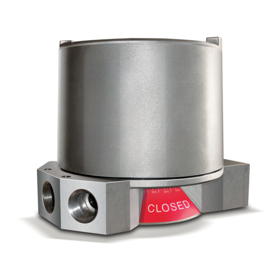
Type VSD Valve Controllers are designed to provide high accuracy feedback of valve position with comprehensive diagnostics, including Partial
Stroke Testing (PST). This document, outlines the essential safety information for installing the device, connecting into the device (including
connecting the primary solenoid) and the connection to and setting of the independent feedback systems. Additional connections to and operation
of the Valve Diagnostic/PST system within the device are covered by document VSD-IOM-001.
Installation - Mounting
Attach mounting plate (1) to the actuator using fasteners (2) and lockwashers (2a) provided with mounting kit (if supplied by Imtex).
Loosen indicator cover set screw (3) and rotate indicator cover (4) to desired viewing angle. Retighten set screw (3).
Fit VSD assembly to actuator ensuring that the NAMUR coupler (7) engages the shaft of the actuator (9). If a torque coupler (7a) is
used instead of the NAMUR Coupler on Non-NAMUR actuators, ensure this is securely fitted to the underside of the controller using the screw,
flatwasher and lockwasher supplied (7b/7c/7d) before fitting over the flats on the actuator shaft (9).Secure the assembly using the screws (10) and
lockwashers (11) provided with the mounting kit. Eccentricity of the shaft must not exceed 0.25mm.
If it should be necessary, re-align controller by loosening mount screws (10). Retighten screws when satisfied with alignment.
Fine tune the indicator cover (4) by loosening set screw (3). Retighten set screw when completed.
Installation - Wiring and Setting Internally Wired Transmitter and Independent Switches
Once the controller is fitted to the actuator, remove cover (12) by loosening 2 x cover lock screws (13).
Bring field wiring into the enclosure via the conduit entries (14) fitted with a suitable cable gland. Use blanking plugs to block off any un-used cable
entries. If wiring in the actuator solenoid(s) or additional components, bring these into the enclosure using conduit entries 14a to facilitate wiring.
NOTE: Suitable IP6x rated cable glands, blanking plugs and thread adaptors must be used to maintain controller IP rating. On flameproof enclosures,
only ATEX/IECEx certified Exd cable gland, blanking plugs and thread adaptors can be used. Blanking plugs must not be used with a gland adaptor.
Connect wiring to the terminals (15, 15a, 15b) within the enclosure according to the wiring diagram and terminal labelling. Connect earth conductor
(which forms part of the supply cable and MUST be at least equal to the size of the phase conductors ) to the internal earth points (18). Connect
the external earth/equipotential bonding conductor to the controller using the external earth clamp assembly(19). Conductor should be 4mm2 (min)
The next stage of the installation requires the actuator to be stroked. This can be done in a number of ways depending on the configuration of the
controller installed. Document VSD-IOM-001 covers how the actuator might be stroked using the controller. Otherwise, the actuator canbe stroked
using the solenoid(s) backwired into the controller as operated from the control room, (may require a seperate 24VDC power supply to be connected
depending on unit supplied).
The internally wired transmitter is factory set to provide feedback for 90 degree rotation - clockwise to close. If required, the internally wired transmitter
can be re-programmed. NOTE: THIS SHOULD ONLY BE DONE IF CONFIDENT THE TRANSMITTERREQUIRES RESETTING BECAUSE IT IS
PROVIDING AN INVERTED SIGNAL. Clear the transmitter (20) programming by pressing and holding buttons 'A' and 'B' for 2 seconds until the LED
blinks. Drive the actuator to closed position. Press and hold button 'A' for 2 sec until it blinks. Drive the actuator to open position. Press and hold
button 'B' for 2 sec until it blinks.
For controllers fitted with standard cam/spline activated switches/sensors, drive the actuator to the first required indication position and
set the bottom switch by lifting and rotating the bottom cam (16). Secure the cam by allowing it to fully re-engage with the spline (17).
Repeat the process for each switch in-turn by lifting/pushing down the appropriate cam, rotating and re-engaging as desired position is reached.
For controllers with barrel or slotted sensors, or with a transmitter, consult page 2 of these instructions for 'Further Setting Instructions'.
Once completed, verify that indication is as required by fully stroking the actuator. Then refit cover (12) and secure using the 2 x cover lock screws (13).
SPECIAL CONDITIONS FOR SAFE USE OF CERTIFIED ENCLOSURES - ATEX / IECEx
Installation should be carried out by suitably trained personnel to an applicable Code of Practice (eg IEC/EN60079-14 & IEC/EN61241-14).
Only suitably IP and Exd certified and temperature rated cable glands, thread adaptors and blanking plugs are permitted for use
with ATEX/IECEx flameproof enclosures.
The equipment shall not be subjected to a build up of dust and is to be cleaned regularly to prevent dust build up forming on the enclosure.
Where intrinsically safe components are fitted and are to be used within an Intrinsically Safe Circuit, they MUST be supplied by an
ATEX/IECEx approved barrier that is suitable to work with Input Parameters of the respective components
WARNING - For units operating at +85 C, cable, cable glands or conductors in conduit shall be rated +100 C (minimum).
WARNING - Monitor includes external plastic parts and presents an Electrostatic Hazard: Clean Only with a Damp Cloth.
WARNING - Do not install on an external source of heating or cooling e.g. by hot/cold air blowing temperature units
WARNING - Locate monitor to prevent propagating brush discharges
WARNING - Monitor should not be opened when energised or an explosive atmosphere may be present. The cover
screws (13) must be loosened before opening and re-tightened before the controller re-enters service.
The maximum constructional gap (i
) is less than that required by
C
Table 1 of IEC 60079-1:2007 clause 5.2.2 as detailed below:
Flamepath
- Through Shaft
Max Gap (mm) - 0.07
Comment
- Cylindrical Spigot Joint
Instructions
7c
7d
7b
Item 7a
3
4
The certification for this monitor relies upon the following materials used in its construction:
- Stainless Steel
- EDPM 70
If the equipment is likely to come into contact with aggressive substances, then it is the responsibility
of the user to take suitable precautions that prevent it from being adversely affected, thus ensuring
that the type of protection provided by the equipment is not compromised. Aggressive substances
might be: acidic liquids or gases that attack Stainless Steel, or direct and prolonged contact with some
Hydrocarbons that could affect the seals. Regular checks/inspections should be carried out if aggressive
substances are present.
CHK'D
ECO
REV
DRAWN
DATE
28.2.13
13-2019
PT
A
17-2618
PT
14.2.17
B
18-2692
PT
1.2.18
Imtex Controls Limited
Tel:+44(0)8700-340002
Website: www.imtex-controls.com
Reference Diagram
15b
13
14a
5
20
7
1
2
2a
Additional Instructions for Safe Use
TITLE:
Installation, Operating & Maintenance
VSD - IECEx/ATEX
VSD-IOM-002
DWG NO.
SHEET 1 OF 3
15
15a
18
Button B
14
Button A
19
12
16
17
10
11
9
REV
B
STATUS
R
Advertisement

Summary of Contents for Imtex-Controls VSD-IOM-002
- Page 1 WARNING - Monitor should not be opened when energised or an explosive atmosphere may be present. The cover screws (13) must be loosened before opening and re-tightened before the controller re-enters service. Imtex Controls Limited VSD-IOM-002 The maximum constructional gap (i ) is less than that required by DWG NO.
- Page 2 17-2618 1.2.18 18-2692 VSD - IECEx/ATEX Imtex Controls Limited This private & confidential drawing is the property VSD-IOM-002 DWG NO. of Imtex Controls Limited, Tonbridge, UK and cannot STATUS Tel:+44(0)8700-340002 be copied or reproduced without the express written permission of the Company.
- Page 3 Operating Life: 5,000,000 Cycles Not recommended for use in 24VDC operating at <20mA Imtex Controls Limited This private & confidential drawing is the property VSD-IOM-002 DWG NO. of Imtex Controls Limited, Tonbridge, UK and cannot STATUS Tel:+44(0)8700-340002 be copied or reproduced without the express written permission of the Company.