Table of Contents
Advertisement
Quick Links
MECHATRONIC DRIVES WITH STEPPER MOTOR
Hardware Version V1.3
HARDWARE MANUAL
+
+
TRINAMIC Motion Control GmbH & Co. KG
Hamburg, Germany
www.trinamic.com
PD42-1-
+
PD42-2-
PD42-3-
PD42-4-
Stepper Motor NEMA17 / 42mm
0.22 – 0.7 Nm
with Controller / Driver
up-to 2A RMS / 24V DC
sensOstep™ encoder
RS485, CAN, USB interfaces
+
PANdrives
1140
1140
1140
1140
Advertisement
Table of Contents

Related Manuals for Trinamic PD42-1-1140


Summary of Contents for Trinamic PD42-1-1140
- Page 1 PD42-2- 1140 PD42-3- 1140 PD42-4- Stepper Motor NEMA17 / 42mm 0.22 – 0.7 Nm with Controller / Driver up-to 2A RMS / 24V DC sensOstep™ encoder RS485, CAN, USB interfaces TRINAMIC Motion Control GmbH & Co. KG Hamburg, Germany www.trinamic.com...
-
Page 2: Table Of Contents
11.1 Calculation: Velocity and Acceleration vs. Microstep and Fullstep Frequency ........ 28 12 Revision history ................................30 12.1 Document revision ............................30 12.2 Hardware revision ............................. 30 13 References..................................31 Copyright © 2012-2018, TRINAMIC Motion Control GmbH & Co. KG... -
Page 3: Life Support Policy
PD42-x-1140 Hardware Manual (V1.03 / 2018-JAN-25) 1 Life support policy TRINAMIC Motion Control GmbH & Co. KG does not authorize or warrant any of its products for use in life support systems, without the specific written consent of TRINAMIC Motion Control GmbH &... -
Page 4: Features
PD42-x-1140 Hardware Manual (V1.03 / 2018-JAN-25) 2 Features The PANdrive™ PD42-1-1140, PD42-2-1140, PD-3-1140 and PD42-4-1140 are small and compact full mechatronic solutions including NEMA17 / 42mm flange size stepper motors, the TMCM-1140 controller/ driver electronics and TRINAMIC sensOstep™ encoder for step-loss detection. The four PANdrives include stepper motor with different lengths and different holding torques (PD42-1-1140: 0.22Nm, PD42-2-1140: 0.36Nm, PD42-3-1140: 0.44Nm and... - Page 5 Efficiency with coolStep Efficiency with 50% torque reserve Efficiency Velocity [RPM] Figure 2.2 Energy efficiency example with coolStep Copyright © 2012-2018, TRINAMIC Motion Control GmbH & Co. KG...
-
Page 6: Order Codes
(cable length approx.. 200mm) 1x cable loom for motor connector (cable length approx.. 200mm) 1x USB type A connector to mini-USB type B connector cable Table 3.3: Cable loom order code Copyright © 2012-2018, TRINAMIC Motion Control GmbH & Co. KG... -
Page 7: Mechanical And Electrical Interfacing
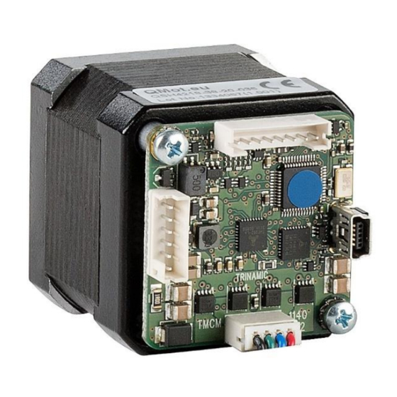
TMCM-1140 controller / driver electronics mounted on its backside and integrated sensOstep™ encoder. The PD42-1-1140 uses the QSH4218-34-20-022 stepper motor with 0.22Nm holding torque, the PD42-2-1140 uses the QSH4218-38-20-036 stepper motor with 0.36Nm holding torque, the PD42-3-1140 uses the QSH4218-47-20-044 stepper motor with 0.44Nm holding torque and the PD42-4-1140 uses the QSH4218-60-20-... -
Page 8: Stepper Motor
COIL Phase inductance (typ.) Holding torque 0.22 0.36 0.44 0.70 Insulation class Rotor inertia g cm Weight 0.22 0.24 0.35 Table 4.1: NEMA 17 / 42mm stepper motor technical data Copyright © 2012-2018, TRINAMIC Motion Control GmbH & Co. KG... -
Page 9: Integrated Sensostep™ Encoder
Use compressed air for cleaning the module if necessary (especially in prototype setups). In order to prevent shorts and better protect the electronics the TMCM-1140 printed circuit board is coated after assembly of components since hardware version V1.3. Copyright © 2012-2018, TRINAMIC Motion Control GmbH & Co. KG... -
Page 10: Connectors
Connector housing JST: PHR-4 Contacts JST: SPH-002T-P0.5S Wire: 0.22mm Mini-USB Molex 500075-1517 Any standard mini-USB plug Connector Mini USB Type B vertical receptacle Table 4.2: Connectors and mating connectors, contacts and applicable wire Copyright © 2012-2018, TRINAMIC Motion Control GmbH & Co. KG... -
Page 11: Power And Communication
Please see also chapter Fehler! Verweisquelle konnte nicht gefunden werden., operating values. There is no reverse polarity protection! The module will short any reversed supply voltage due to internal diodes of the driver transistors. Copyright © 2012-2018, TRINAMIC Motion Control GmbH & Co. KG... - Page 12 There are actually two options which can be recommended: Add resistor (Bias) network on one side of the bus, only (120R termination resistor still at both ends): Copyright © 2012-2018, TRINAMIC Motion Control GmbH & Co. KG...
- Page 13 Host Slave Slave Slave c:> node node node n - 1 termination termination resistor resistor (120 Ohm) (120 Ohm) keep distance as short as possible Figure 4.5 CAN bus structure Copyright © 2012-2018, TRINAMIC Motion Control GmbH & Co. KG...
-
Page 14: Multi-Purpose I/O
STOP_L / STOP_R and HOME switch inputs (alternate function 1) or as encoder input for an external incremental A/B/N encoder with open-collector outputs (pull-ups are not necessary for encoder with push-pull outputs). Copyright © 2012-2018, TRINAMIC Motion Control GmbH & Co. KG... - Page 15 IN_3 TMCL: GAP 9, 0 // get digital value channel, connected to of HOME input processor interrupt input Table 4.5 Multipurpose inputs / alternate functions Copyright © 2012-2018, TRINAMIC Motion Control GmbH & Co. KG...
- Page 16 (relais etc.) above supply voltage (see figure below). OUT_0 should not be connected to any voltage above supply voltage of the module due to the internal freewheeling diode. Copyright © 2012-2018, TRINAMIC Motion Control GmbH & Co. KG...
- Page 17 With TMCL firmware OUT_1 can be switched on (supply +5V to external circuit) using command SIO 1, 2, 1 and off (output pulled low via 10k pull-down resistor) using command SIO 1, 2, 0 (this is also the factory default setting of this output). Copyright © 2012-2018, TRINAMIC Motion Control GmbH & Co. KG...
-
Page 18: Motor
For remote control and communication with a host system the PD42-x-1140 provides a USB 2.0 full-speed (12Mbit/s) device interface (mini-USB connector). As soon as a USB-Host is connected the module will accept commands via USB. Copyright © 2012-2018, TRINAMIC Motion Control GmbH & Co. KG... - Page 19 Motor movements are not possible in this mode. Therefore, always connect a power supply to the Power and Communication Connector for motor movements. Copyright © 2012-2018, TRINAMIC Motion Control GmbH & Co. KG...
-
Page 20: Motor Driver Current
176..183 2.118 1.497 184..191 2.210 1.563 192..199 2.302 1.628 200..207 2.394 1.693 208..215 2.486 1.758 216..223 2.578 1.823 224..231 2.670 1.888 232..239 2.762 1.953 240..247 2.854 2.018 248..255 2.946 2.083 Copyright © 2012-2018, TRINAMIC Motion Control GmbH & Co. KG... -
Page 21: Reset To Factory Defaults
Remove short between pads After switching on power-supply / connecting USB cable all permanent settings have been restored to factory defaults Short these two pads Figure 6.1 Reset to factory default settings Copyright © 2012-2018, TRINAMIC Motion Control GmbH & Co. KG... -
Page 22: On-Board Leds
Status Label Description Heartbeat This green LED flashes slowly during operation. Error Error This red LED lights up if an error occurs. Green LED Red LED Figure 7.1 On-board LEDs Copyright © 2012-2018, TRINAMIC Motion Control GmbH & Co. KG... -
Page 23: Operational Ratings
Maximum bit rate supported on RS485 RS485 connection 1000000*) Table 8.3: Operational ratings of RS485 interface *) TMCM-1140 hardware revision V1.2: max. 115200 bit/s, TMCM-1140 hardware revision V1.3: max. 1Mbit/s Copyright © 2012-2018, TRINAMIC Motion Control GmbH & Co. KG... - Page 24 Parameter Unit Number of nodes connected to single RS485 > 110 network Maximum bit rate supported on CAN 1000 1000 kbit/s connection Table 8.4 Operational ratings of the CAN interface Copyright © 2012-2018, TRINAMIC Motion Control GmbH & Co. KG...
-
Page 25: Torque Curves
PD42-1-1140 - 2A RMS Phase Current, 256 uSteps 0,30 0,25 0,20 0,15 0,10 0,05 0,00 1000 10000 speed[rpm] Figure 9.1 PD42-1-1140 torque vs. velocity 24V / 2A, 256µsteps 9.1.2 PD42-2-1140 Torque Curve PD42-2-1140 - 2A RMS Phase Current, 256 uSteps 0,45 0,40 0,35 0,30 0,25 0,20 0,15... -
Page 26: Pd42-3-1140 Torque Curve
PD42-4-1140 - 2A RMS Phase Current, 256 uSteps 0,80 0,70 0,60 0,50 0,40 0,30 0,20 0,10 0,00 1000 10000 speed[rpm] Figure 9.4 PD42-4-1140 torque vs. velocity 24V / 2A, 256µsteps Copyright © 2012-2018, TRINAMIC Motion Control GmbH & Co. KG... -
Page 27: Functional Description
The PD42-x-1140 with TMCL™ firmware option is supported by the PC based software development environment TMCL-IDE for the Trinamic Motion Control Language (TMCL™). Using predefined TMCL™ high level commands like move to position a rapid and fast development of motion control applications is guaranteed. -
Page 28: Pd42-X-1140 Operational Description
The change in the pulse rate per time unit (pulse frequency change per second – the acceleration a) is given pulse ramp This results in acceleration in fullsteps of: with af: acceleration in fullsteps usrs Copyright © 2012-2018, TRINAMIC Motion Control GmbH & Co. KG... - Page 29 ALCULATION OF THE NUMBER OF ROTATIONS A stepper motor has e.g. 72 fullsteps per rotation. 1907 fullsteps rotation 1907 1589 fullsteps rotation Copyright © 2012-2018, TRINAMIC Motion Control GmbH & Co. KG...
-
Page 30: Revision History
Figure 12.1: Document revision 12.2 Hardware revision Please note: all current PD42-1-1140, PD42-2-1140, PD42-2-1140 and PD42-4-1140 PANdrives™ use controller driver electronics TMCM-1140 V1.3. Previous versions used TMCM-1140 V1.2. All other TMCM-1140 hardware versions listed below have been used for prototypes, only. The following list includes changes in hardware for the TMCM-1140 controller / driver electronics since initial hardware (prototype) version V1.0:... -
Page 31: References
USB-2-485 interface converter Additional information can be found on http://www.trinamic.com. [TMC429] TMC429 datasheet Additional information can be found on http://www.trinamic.com. [TMC262] TMC262 datasheet Additional information can be found on http://www.trinamic.com. Copyright © 2012-2018, TRINAMIC Motion Control GmbH & Co. KG...
Need help?
Do you have a question about the PD42-1-1140 and is the answer not in the manual?
Questions and answers