
Summary of Contents for MAS Elettronica SARA
- Page 1 SARA Single Board Computer Hardware User Manual SARA Hardware User Manual VERSION 1.0...
- Page 2 Revision History: Doc. Version SARA Version Date Change V1.0 REV1 2020-04-20 Initial Version...
-
Page 3: Table Of Contents
2.3.8 USB HOST Interface (CN11) ..............25 2.3.8 Expansion Interface (CN12) ............... 26 2.3.9 Power In Interface (CN1) ................28 2.3.10 SARA Pin Functional ................29 2.4.1 Electrical Characteristics ................30 2.4.2 Mechanical Characteristics ................. 31 SARA Hardware User Manual VERSION 1.0... -
Page 4: Chapter 1 Product Overview
1 . 1 1.1.1 Hardware The single board computer SARA which has an expansion board to carry the AURA i.MX6ULL is one of our design of the base plate . The flexible design allows the fast and easy way of realizing and upgrading the controller’s capabilities. In additional to those features offered by AURA i.MX6ULL, the SARA features 6 serial ports (6... - Page 5 Size 100 x 85 x 19mm 100 x 85 x 19mm 100 x 85 x 19mm Temperature 0° 70° C 0° 70° C -0° 70° C Support OS Linux 4.X Linux 4.X Linux 4.X SARA Hardware User Manual VERSION 1.0...
-
Page 6: Chapter 2 Hardware System
Hardware System 2.1 Block Diagram Figure 1 SARA Block Diagram 2.2 Main Features SARA provides the following features and communication interfaces: ■1x RJ45 Ethernet (10/100 Mbit) ■2x USB 2.0 port through on board USB HUB ■1x TF 24-bit ■1x DDR3 STD connector ■1x Digital RGB interface (up to 16 bit colour) - Page 7 ■1x Debug UART (3.3V TTL) ■1x DC-IN jack with 9.6~14.4V ■LEDs SARA Hardware User Manual VERSION 1.0...
-
Page 8: Connector Locations
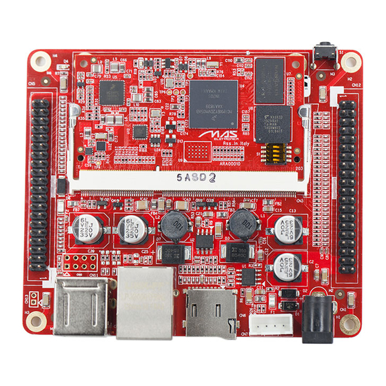
2.3 Hardware Interfaces 2.3.1 Connector Locations Figure 3 SARA Interface... -
Page 9: Core Module Interface (Cn3)
Digital ground Not connected Not connected Not connected Not connected Digital ground VIO_3V3 3.3V main power supply 3.3V Not connected VIO_3V3 3.3V main power supply 3.3V Not connected Not connected VBATBAKUP RTC backup power supply SARA Hardware User Manual VERSION 1.0... - Page 10 Signal name Description Power rail Note Digital ground Not connected Digital ground USB1_VBUS USB1 power supply Not connected USB1_ID Use this pin to detect the ID pin if you use USB OTG. Not connected GPIO_5_4 GPIO USB0_ID Use this pin to detect the ID pin if you use USB OTG.
- Page 11 100/1000M linked LED 2.5V Digital ground PF3000_SW1AFB_3V3 2.5V power supply 2.5V JTAG_nTRST JTAG TRST 3.3V Not connected JTAG_TMS JTAG DATA 3.3V LCD_DATA2 LCD_DATA2 (gpio) 3.3V JTAG_TDI SPI data 3.3V LCD_DATA8 LCD_DATA8 (gpio) 3.3V JTAG_TCK JTAG_CLK 3.3V SARA Hardware User Manual VERSION 1.0...
- Page 12 Signal name Description Power rail Note LCD_DATA9 LCD_DATA9 (gpio) 3.3V Digital ground Not connected RESET_OUT Not connected Not connected PF3000_VLDO4_ADJ 1.8V power supply 1.8V Not connected JTAG_SYS_RST Digital ground PF3000_SW1AFB_3V3 MMC/SD/SDIO power supply 3.3V Digital ground BUTT_RESET Reset input 3.3V UART6_TX UART transmit data 3.3V...
- Page 13 UART receive data 3.3V UART3_RX UART receive data 3.3V Digital ground UART2_RX UART receive data 3.3V Not connected UART2_TX UART transmit data 3.3V Not connected Digital ground JTAG_TDO 3.3V Not connected ENET2_TX_CLK ENET2_TX_CLK 3.3V SARA Hardware User Manual VERSION 1.0...
- Page 14 Signal name Description Power rail Note Digital ground ENET2_TX_TXEN ENET2_TX_TXEN/ 3.3V ENET2_RXD0 ENET2_RXD0/ 3.3V ENET2_TXD1 ENET2_TXD1/ 3.3V ENET2_TX_CLK ENET2_TX_CLK/ 3.3V Not connected Digital ground LCD_DATA0 LCD data bus Not Connected LCD_DATA1 LCD data bus Digital ground Not connected I2C2_SCL I2C clock 3.3V Not connected I2C2_SDA...
- Page 15 3.3V SAI1_RX_DATA McASP0 serial data (in/out) 3.3V ADC3 Analog input/output 3.3V SAI1_TX_DATA McASP0 serial data (in/out) 3.3V ADC2 Analog input/output 3.3V Digital ground ADC1 Analog input/output 3.3V ENET2_TXD0 3.3V Digital ground ENET2_CRS_DV 10 3.3V SARA Hardware User Manual VERSION 1.0...
- Page 16 Signal name Description Power rail Note Not connected Not connected Not connected Digital ground Digital ground ENET2_RXER GPIO 3.3V LCD_DATA3 LCD data bus 3.3V SAI1_RX_SYNC GPIO 3.3V LCD_DATA4 LCD data bus 3.3V Digital ground LCD_DATA5 LCD data bus 3.3V SAI1_RX_BCLK GPIO 3.3V LCD_DATA6...
- Page 17 LCD_DATA22 LCD data bus 3.3V GPIO5_5 GPIO 3.3V LCD_DATA23 LCD data bus 3.3V GPIO5_6 GPIO 3.3V Digital ground GPIO5_7 GPIO 3.3V LCD_PCLK LCD pixel clock 3.3V CSI_VSYNC GPIO 3.3V LCD_VSYNC LCD vertical sync 3.3V SARA Hardware User Manual VERSION 1.0...
-
Page 18: Ethernet Interface (Cn4)
Signal name Description Power rail Note CSI_HSYNC GPIO 3.3V LCD_HSYNC LCD horizontal sync 3.3V CSI_DATA0 GPIO 3.3V LCD_EN LCD enable 3.3V LCD_DATA17 GPIO 3.3V Digital ground LCD_DATA16 GPIO 3.3V LED_PWM LCD PWM Control 3.3V GPIO5_9 GPIO 3.3V Digital ground Digital ground 2.3.3 Ethernet Interface (CN4) Type: RJ45 Signal name... -
Page 19: Expansion Interface (Cn5)
3.3V VCC5V 5V power supply I2C1_SDA I2c1 data 3.3V VCC5V 5V power supply I2C1_SCL I2c1 clock 3.3V Digital ground ENET2_RXER GPIO 3.3V UART6_TX UART transmit data 3.3V Digital ground UART6_RX UART receive data 3.3V SARA Hardware User Manual VERSION 1.0... - Page 20 Signal name Description Power rail Note Address latch enable 3.3V LCD_DATA2 Read enable 3.3V Write enable 3.3V Digital ground LCD_DATA9 Command latch enable 3.3V ENET1_RXD0 Ready/busy 3.3V VIO_3V3 3.3V main power supply 3.3V Write project 3.3V JTAG_TMS JTAG 3.3V Digital ground JTAG_TDI JTAG 3.3V...
-
Page 21: Tf Interface (Cn6)
MMC/SD/SDIO data bus 3.3V CD/DAT3 MMC/SD/SDIO data bus 3.3V MMC/SD/SDIO command 3.3V 3.3V power supply 3.3V CLOCK MMC/SD/SDIO clock 3.3V Digital ground DAT0 MMC/SD/SDIO data bus 3.3V DAT1 MMC/SD/SDIO data bus 3.3V SD card detect 3.3V SARA Hardware User Manual VERSION 1.0... -
Page 22: Debug Interface (Cn7)
2.3.6 Debug Interface (CN7) Type: Header Male 1x4 2.54mm pitch Signal name Description Power rail Note VIO_3V3 3.3V main power supply 3.3V UART1_TX UART transmit data 3.3V UART1_RX UART receive data 3.3V Digital ground 2.3.7 LCD Interface (CN8) Type: FPC 50 Pin Signal name Description I/O Power rail... - Page 23 AC bias control (STN) or pixel data enable (TFT) 3.3V HSYNC LCD Horizontal Sync 3.3V VSYNC LCD Vertical Sync 3.3V Digital ground LCD Pixel Clock 3.3V Digital ground X+ Position Input 3.3V X- Position Input 3.3V SARA Hardware User Manual VERSION 1.0...
- Page 24 Signal name Description I/O Power rail Note Y+ Position Input 3.3V Y- Position Input 3.3V SPI Clock/GPIO I/O 3.3V GPIO5_0 SPI data 0/GPIO I/O 3.3V SPI data1/GPIO I/O 3.3V SPI chip select/GPIO I/O 3.3V Digital ground I2C2_CLK I2C master serial clock 3.3V I2C2_DAT I2C serial bidirectional data...
-
Page 25: Usb Host Interface (Cn11)
Type: Double USB Host Connector Signal name Description Power rail Note 5V power supply Negative differential USB signal Positive differential USB signal Digital ground 5V power supply Negative differential USB signal Positive differential USB signal Digital ground SARA Hardware User Manual VERSION 1.0... -
Page 26: Expansion Interface (Cn12)
2.3.8 Expansion Interface (CN12) Type: Pin Header 2x20 2.54mm pitch Signal name Description Power rail Note VIO_3V3 3.3V main power supply 3.3V VIO_3V3 3.3V main power supply 3.3V NET2_CRS_DV MII receive data error 3.3V UART6_TX UART transmit data 3.3V ENET2_TXD0 ETHERNET 2 TXD0 3.3V UART6_RX... - Page 27 3.3V CSI_HSYNC GPIO 3.3V GPIO5_9 GPIO 3.3V CSI_DATA0 GPIO 3.3V Digital ground Digital ground VSYSTEM Main power supply 9V~15V VCC5V 5V main power supply VSYSTEM Main power supply 9V~15V VCC5V 5V main power supply SARA Hardware User Manual VERSION 1.0...
-
Page 28: Power In Interface (Cn1)
2.3.9 Power In Interface (CN1) Type: Power DC JACK Signal name Description Power rail Note DC IN Power DC In 9~15V Digital ground Digital ground... -
Page 29: Sara Pin Functional
2.3.10 SARA Pin Functional SARA Hardware User Manual VERSION 1.0... -
Page 30: Electrical Characteristics
2.4 Technical Specitfications 2.4.1 Electrical Characteristics Table 2.4.1-1 Absolute Maximum Ratings Symbol Description Input/Output Type Max Unit VSYSTEM Main power supply Input -0.3 12.6 Ivsystem Main power current Input VBAT Main power supply Input -0.3 VIO_3V3 Digital power supply Input -0.3 VBATBAKUP RTC power supply... -
Page 31: Mechanical Characteristics
2.4.2 Mechanical Characteristics AURA Dimension : Unit : mm SARA Hardware User Manual VERSION 1.0... - Page 32 SARA Dimension : Unit : mm...
- Page 33 Technical Support and Warranty Technical Support MAS Elettronica provides its product with one-year free technical support includ- ing: 1. Providing software and hardware resources related to the embedded prod- ucts of MAS Elettronica; 2. Helping customers properly compile and run the source code provided by MAS Elettronica;...
- Page 34 4 Please contact technical support if there is any repair request. Note: • MAS Elettronica will not take any responsibility on the products sent back without the permis- sion of the company.
- Page 35 Contact Information Phone: +39-0498687469 Sales: sm@maselettronica.com Support: support@maselettronica.com Website: http://www.maselettronica.com Address: Via Rossi 1 35030 Rubano (PD) Italy SARA Hardware User Manual VERSION 1.0...
Need help?
Do you have a question about the SARA and is the answer not in the manual?
Questions and answers