Advertisement
Quick Links
Genetix GCM Configuration and Troubleshooting for DF-1
Both serial ports in a Genetix GCM can be configured to support Allen-Bradley DF-1 point to
point protocol. This allows for establishing direct communications to Allen-Bradley PLCs, using
•
Ch0, usually the built-in serial port,
•
DeviceNet using the 1761-NET-DNI interfaces,
•
EtherNet/IP using 1761-NET-ENI interfaces, or
•
Data Highway Plus using KF2 or similar interfaces.
We currently support all methods described above.
The host can take control over and/or monitor the GCM, using CIT data table exchange. For
details of the CIT structure, see
System Requirements
All versions of the Merrick Genetix GCM controller support Allen-Bradley (A-B) DF-1 Serial
Communications protocol and exposes a standardized Common Interface Table (CIT),
compatible with the A-B "Common Interface File" (CIF) specification. PCCC functions 1 (PLC2
Unprotected Read, 485CIF Read), 8 (PLC2 Unprotected Write, 485CIF Write) and 6 (PLC-2
Diagnostic Status) are supported.
The physical interface is normally 3-wire RS232, but 4-wire RS-422 can also be used. The host
or interface is assumed to maintain a cyclic conversation with the GCM, which exposes a
Common Interface Table (CIT), making it possible to monitor and/or supervise the GCM
completely.
Different data types are used for control/status bits, integer numbers and floating-point numbers.
Control/Status bits and Integer numbers are organized in 16 bit words. Parameters are organized
as IEEE 32 bit floating point numbers, located in two consecutive 16 bit words. For PLC's that
don't support floating point numbers, it is possible to split parameters into two 16 bit integers, one
containing the integer part and one containing the fractional part multiplied by 10,000 (four
implied decimal places).
Configuring the GCM
Configuring the GCM includes setting up communications parameters, register tags, warnings,
faults and external inputs and outputs. The register tags are set to make any internal GCM
parameter appear in Tag 1 R to Tag 5 R values. Standard feeder parameters are always
available. Warnings and faults are user preference qualified, associated with any logical I/O point
in the GCM. This configuration is done regardless if communications is used or not. Any logical
inputs you want to control from the PLC must be mapped to a network input. In the same way,
logical outputs must be mapped to network outputs for monitoring purposes.
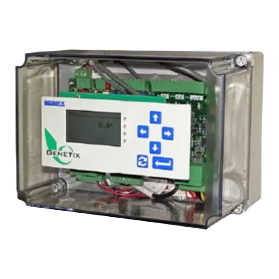
It is recommended that you use the built in Terminal Monitoring and Configuration Interface
(TMCI) for setting up, troubleshooting and monitoring the DF-1 interface.The following menu
references and screen shots were taken using the GCM 101.1.6.8 Belt Feeder Controller
application. Operation and Maintenance Manuals as well as register specifications are available
at the Merrick Web Site:
http://www.merrick-inc.com/mct/GENApps/GENApps.htmTo enable network control parameters,
set Advanced Setup, Configuration, Network IO to Y.
http://www.merrick-inc.com/mct/GCMDF1.pdf
Genetix GCM Configuration and Troubleshooting for DF-1
http://www.merrick-inc.com/mct/CIT.PDF
Page 1
Merrick Industries, June 2011
2011-06-14/Lars
Advertisement

Subscribe to Our Youtube Channel
Related Manuals for MERRICK Genetix GCM


Summary of Contents for MERRICK Genetix GCM
- Page 1 Merrick Industries, June 2011 Genetix GCM Configuration and Troubleshooting for DF-1 Both serial ports in a Genetix GCM can be configured to support Allen-Bradley DF-1 point to point protocol. This allows for establishing direct communications to Allen-Bradley PLCs, using •...
- Page 2 Bit 4, 5 Parity Select – 00: Odd, 01: Even, 10: Forced 1, 11: Forced 0 Bit 6 Enable Break transmission. Always 0! Bit 7 DLAB Access. Always 0! Typical setting is 0x03 for N, 8, 1 (most commonly used) Page 2 2011-06-14/Lars http://www.merrick-inc.com/mct/GCMDF1.pdf...
- Page 3 The warning and faults are normally set up using the user interface; Advanced Setup, Digital I/O, Warings/Faults. Warning bits (CIT word 18) and Fault bits (CIT word 19) go on whenever the corresponding logical inputs or outputs go on and stay on until they are deliberately cleared. Faults and Page 3 2011-06-14/Lars http://www.merrick-inc.com/mct/GCMDF1.pdf...
- Page 4 This is how the inputs and outputs have to be mapped in the GCM for this example: Logical Physical CIT Word:Bit Run Permission GCM Input 1 41:8 Belt Drv Fail GCM Input 3 41:10 Netw Run Perm. Netw Input 1 45:0 Belt Forward GCM Output 1 42:8 Page 4 2011-06-14/Lars http://www.merrick-inc.com/mct/GCMDF1.pdf...
- Page 5 (Rx+ and Rx-), and transmits, after being correctly addressed, on terminals 8 and 9 (Tx+ and Tx- Pair Part GCM Terminal RS-422 Name Shield The RS485 interface also allows for up to 50V common mode swing with respect to the 24V DC negative terminal on the GCM. Page 5 2011-06-14/Lars http://www.merrick-inc.com/mct/GCMDF1.pdf...
- Page 6 Ground. For some hosts, it may be better to connect the shield to pin 4, RS232 GND. This picture shows a GCM connected to an end point of a 4-wire RS422 line. Note the terminating resistors. Page 6 2011-06-14/Lars http://www.merrick-inc.com/mct/GCMDF1.pdf...
- Page 7 65 in[21] Tag 3 Reg 41 in[25] PhIn 5102 66 in[22] Tag 4 Reg 42 in[26] Ph Out L/H 0902/0000 67 in[23] Tag 5 Reg X to change port addr: 44|size: 8|CSErrs: 0|Timee: rxfme: 0|rxlfm: 0|rtgms: 3496|ttgms: 1748 Page 7 2011-06-14/Lars http://www.merrick-inc.com/mct/GCMDF1.pdf...
- Page 8 UART Interrupt counter. Increments for any serial activity. Since the UARTs have 16 byte FIFOs, this counter typically increments slower than Rxchs and Txchs. Rxchs Received characters counter Txchs Transmitted characters counter Rxuae Receiver UART error counter. Page 8 2011-06-14/Lars http://www.merrick-inc.com/mct/GCMDF1.pdf...
- Page 9 Character transmitter state enumeration: 0 Idle 1 First character in UART, RS485 transmitter enabled 2 Ongoing transmission from ISR 3 Last byte of telegram placed in UART FIFO 4 Waiting for UART transmitter empty to disable the RS485 transmitter Page 9 2011-06-14/Lars http://www.merrick-inc.com/mct/GCMDF1.pdf...
- Page 10 An “x” indicates that the telegram will be ignored for the format error. An empty field indicates that the specific format error does not apply for this protocol. Rxlf Format error Page 10 2011-06-14/Lars http://www.merrick-inc.com/mct/GCMDF1.pdf...
- Page 11 The integrity bit can be monitored in the TCMI CIT Diagnostic Screen (P1), and the GCM can be set up to monitor the activity of the integrity bit, potentially generating a Warning or Fault if the bit stops toggling. Page 11 2011-06-14/Lars http://www.merrick-inc.com/mct/GCMDF1.pdf...
Need help?
Do you have a question about the Genetix GCM and is the answer not in the manual?
Questions and answers