Table of Contents
Advertisement
Quick Links
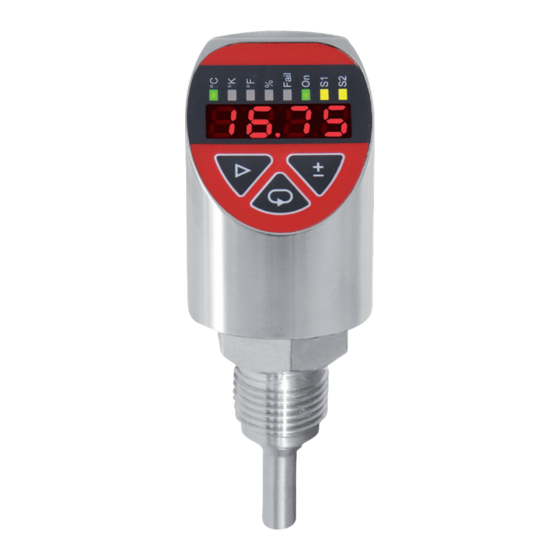
Thermocont TS4S
Temperature switch for general applications
Monitoring of temperatures
in gases, vapors, liquids and dust
Technical manual
07.17
Applications
General applications in
Machinery and plant engineering
•
•
Air-conditioning and refrigeration plant engineering
Hydraulic and pneumatic systems
•
Process industry
•
•
Environmental technology
Main features
Wide range of applications
Wide process temperature range –99,9°C to +500°C
•
High process pressure tightness up to 100 bar
•
•
Wide variety of process connections
High protection class IP65 / IP67
•
Wide environmental temperature range –40°C to +85°C
•
Long term stable temperature sensor platinum Pt100 class A – DIN EN
60751
Increased process safety and cost saving by self-supervising
measuring system for drift monitoring and redundancy function
High accuracy – characteristic deviation ≤ 0,5% of measuring range
Short response time
Integrated evaluation electronic
•
Digital display, function LED's, keyboard
2x PNP switch output
•
1x current output 4...20mA
•
•
Connector plug M12
High operating comfort
Enclosure and display rotatable for optimal operability in each
•
installation position
Robust high brightness LED display for best readability
•
3-key operation without additional assistance with tactile feedback
•
Advertisement
Table of Contents

Subscribe to Our Youtube Channel
Summary of Contents for ACS contsys Thermocont TS4S
- Page 1 Thermocont TS4S Temperature switch for general applications Monitoring of temperatures in gases, vapors, liquids and dust Technical manual 07.17 Applications General applications in Machinery and plant engineering • • Air-conditioning and refrigeration plant engineering Hydraulic and pneumatic systems • Process industry •...
- Page 2 You have purchased a high-grade and modern measuring device of ACS-CONTROL-SYSTEM GmbH. We want to give thanks for your purchase and for your confidence to us. The actual technical manual includes instructions for installation, electrical connection and inauguration, as well as the technical data of the device. Modifications, that answer the purpose of the technical progress, are reserved by ACS-CONTROL-SYSTEM GmbH without prior notice.
- Page 3 1 Index 1 System description . . . . . . . . . . . . . . . . . . . . . . . . . . . . . . . . . . . . . . . . . . . . . . . . 4 Intended use ...........
-
Page 4: System Description
1 System description 1 .1 Intended use The device is an electronic temperature switch for monitoring, control as well as continuous measurement of temperatures in gases, vapors, liquids and dusts. The operational reliability of the device is ensured only at the intended use. 1 .2 Field of application Due to the device construction with Process temperature from up to –99,9°C to +500°C... -
Page 5: System Components
Customer specific special versions can be realized short-term on request, e.g. software adaption (menu navigation, special functions, etc.), • changed terminal assignment resp. connector orientation, • design adaption of the user surface, • special designs for the process connection • thread connection acc. -
Page 6: Safety Notes
2 Safety notes 2 .1 Operational safety The device is safely built and tested according to state-of-the-art technology and has left the factory in perfect condition as regards technical safety. The device meets the legal requirements of all relevant EU directives. This is confirmed by attaching the CE mark. -
Page 7: Installation Place
3 Installation The correct function of the device within the specific technical data can only be guaranteed, if the permitted process and environmental temperatures (see chapter „Technical data“) will not be exceeded. 3 .1 Installation place The choice of the place of installation of the sensor and the length of the sensor tube are of considerable importance for the quality and the reliability of the measuring results. -
Page 8: Process And Environmental Temperature
3 .2 Process and environmental temperature At high process temperatures a heat transfer to the terminal enclosure can be reduced by isolation of the medium carrying part of the plant or by the use of a neck tube. 3 .2 .1 Neck tube The neck tube is used to decouple the temperatures between medium and the terminal enclosure in order to reduce the temperature at the terminal enclosure. -
Page 9: Electrical Connection
Electrical connection The electrical connection of the device must be carried out according to the respective country specific standards. Incorrect installation or adjustment could cause applicationally conditioned risks. Warning! The instrument may only be installed if the supply voltage is switched off. 4 .1 Potential equalization - earthing The device must be grounded. -
Page 10: Connection Scheme
4 .6 Connection scheme Conductor color standard connection cable M12 – A-coded: BN = brown • WH = white • BU = blue • BK = black • GY = grey • 1 .1 .1 Electronic output type A 2x switch PNP, supply 24VDC 1 .1 .2 Electronic output type B 1x signal 4…20mA, 1x switch PNP, supply 24VDC 1 .1 .3 Electronic output type C... -
Page 11: Operation And Display Parts
5 Operation 5 .1 Operation and display parts A – LED display • Display of measuring value and operation menu B - Key Set • Access to operation menu In the selection menu entering the selected sub menu • In the set menu applying the new value •... - Page 12 5 .2 .2 Programming mode Access to the function menus by the key Set. In the switch function menu – password 1903 – all the adjustable parameter and functions are • chosen especially for the use of the device as switch. In the transmitter function menu –...
-
Page 13: Current Output
5 .3 .5 Window function The window function realizes a signal range – acceptance region –, where the switch output is set to a definitive switch state. The switch range is determined by input the switch point and switch back point. The switch output is activated, if the current measuring value is inside the area that is defined by the switch point and the reset switch point and if the set switch point delay time has been expired. -
Page 14: Self-Supervising Function
5 .5 Self-supervising function 5 .5 .1 Drift monitoring function The drift monitoring function is only adjustable at devices with option self-supervising. Each sensor element that is used for the recording of temperatures has the unavoidable characteristic a specific behavior concerning long term drift and ageing. This behavior is very similar if not identically at physically equal-type sensor elements like e.g. -
Page 15: Menu Structure
5 .6 Menu structure 5 .6 .1 Menu structure switch function - password 1903 ACS-CONTROL-SYSTEM GmbH l Lauterbachstr. 57 l D-84307 Eggenfelden l www.acs-controlsystem.de l info@acs-controlsystem.de... - Page 16 5 .6 .2 Menu structure transmitter function - password 3009 ACS-CONTROL-SYSTEM GmbH l Lauterbachstr. 57 l D-84307 Eggenfelden l www.acs-controlsystem.de l info@acs-controlsystem.de...
- Page 17 5 .6 .3 Menu structure switch point - password 1111 ACS-CONTROL-SYSTEM GmbH l Lauterbachstr. 57 l D-84307 Eggenfelden l www.acs-controlsystem.de l info@acs-controlsystem.de...
-
Page 18: Parameter Overview
5 .7 Parameter overview Menu group Function Input Description Password input for the access to the transmitter function menu codE 3009 1903 Password input for the access to the switch function menu Password input for the access to the switch point menu 1111 Menu group Function... - Page 19 Menu group Function Input Description Switch output 2 – includes all parameters concerning the switch output 2 Adjustment with applied signal – The actual applied temperature value is captured as switch SP_2 NSiG point resp. upper switch point Adjustment without applied signal – The actual switch point / upper switch point is shown in oSiG the display and can now be adjusted by the operation keys +/- and >.
- Page 20 Menu group Function Input Description Service – includes all parameters concerning service purposes Input of the system damping for reassuring of cyclic fluctuating temperature signals. The adjustment range is 0...40 seconds, in steps of 0,1 seconds No error recorded in the error memory. ErrN A wire break at the internal connections of the sensor element has been detected.
-
Page 21: Error Indication At Operation
5 .8 Error indication at operation The red error indication LED indicates the exceedance of operation limit values, faulty inputs or also device errors. The information, what reason has led to an error indication can be found in each of the two function menus in the area extended functions of the menu point service. -
Page 22: Maintenance
6 Service 6 .1 Maintenance The device is free of maintenance. Special substances can lead to solid coatings on the sensor. Seized depositions can lead to faulty measurement results. In the case of coat forming liquids the sensor must be regularly cleaned e.g. with clear water. Don’t use sharp resp. -
Page 23: Technical Data
7 Technical Data 7.1 Auxiliary power supply Supply voltage U 10,5…35V , reverse polarity protected Residual ripple U ≤ 2V ≤ U ≤ U Smin Smax Supply current I ≤ 60mA Current output max. 22,5mA Switch output with no load 7.2 Output 7.2.1 Analogue output –... -
Page 24: Process Conditions
Characteristic deviation Display / Switch output 3) 5) 8) ≤ ±(0,4K + 0,002 * [t]) [t] = process temperature in °C, no sign, unit K ≤ ±0,6% FS Current output ≤ ±(characteristic dev. display / switch output + 0,1% FS ≤... -
Page 25: Environmental Conditions
7.5 Environmental conditions Environmental temperature -40°C...+85°C Protection IP65/IP67 (EN/IEC 60529) Climatic classification 4K4H (EN/IEC 60721-3-4) Shock classification 50g [11ms] (EN/IEC 60068-2-27) Vibration classification 10g (L1/L2 ≤ 100mm) [10…2000 Hz] (EN/IEC 60068-2-6) 2g (L1/L2 > 100mm) [10…2000 Hz] (EN/IEC 60068-2-6) EM compatibility Operation device class B / Industrial range (EN/IEC 61326) Tightening torque ≤... -
Page 26: Dimension Drawings
8 Dimension drawings 8 .1 Terminal enclosure 8 .2 Process connection Type 0 – without thread Type 1 – Thread ISO 228-1 – G½”B ACS-CONTROL-SYSTEM GmbH l Lauterbachstr. 57 l D-84307 Eggenfelden l www.acs-controlsystem.de l info@acs-controlsystem.de... -
Page 27: Sensor Tube
Type 3 – Thread ISO 228-1 – G¼”B Type 4 / type 5 – Thread ISO 228-1 – G½”B, front-flush gasket 8 .3 Sensor tube ACS-CONTROL-SYSTEM GmbH l Lauterbachstr. 57 l D-84307 Eggenfelden l www.acs-controlsystem.de l info@acs-controlsystem.de... -
Page 28: Ordering Information
9 Ordering information 9.1 Order code Type TS4S Standard Measuring system Resistance sensor Pt100-A Resistance sensor Pt100-A / semiconductor sensor, self-supervision function Approval Standard Process connection without thread, for compression fitting Thread ISO 228-1 – G½”B Thread ISO 228-1 – G¼”B Thread ISO 228-1 –... -
Page 29: Additional Options
9.2 Additional options For the device additional options are available. The respective abbreviation subsequently follows the order code. • LABS-free, silicone-free / paint compatible version • Measurement point designation / TAG – Laser marking • Customer label on device – Laser marking •...
Need help?
Do you have a question about the Thermocont TS4S and is the answer not in the manual?
Questions and answers