Table of Contents
Advertisement
Quick Links
Advertisement
Table of Contents

Summary of Contents for Zodiac Aerospace GPS
- Page 1 Document No.: MUT100072E1R3 02 – 2019 GNSS Receiver Module User’s Manual...
- Page 2 THIS DOCUMENT IS THE PROPERTY OF ZODIAC DATA SYSTEMS UNDER THE COPYRIGHT LAWS, IT MUST NOT BE REPRODUCED OR TRANSMITTED IN ANY FORM, ELECTRONIC OR MECHANICAL, INCLUDING PHOTOCOPYING, RECORDING, STORING IN AN INFORMATION RETRIEVAL SYSTEM, OR TRANSLATING, IN WHOLE OR IN PART WITHOUT PRIOR WRITTEN APPROVAL OF ZODIAC DATA SYSTEMS ZODIAC DATA SYSTEMS RESERVES THE RIGHT TO AMEND THIS USER’S MANUAL WITHOUT NOTICE...
-
Page 3: Table Of Contents
TABLE OF CONTENT 1. INTRODUCTION ................1 About this User’s Manual . - Page 4 8. GLOSSARY ................. 29 GPS — User’s Manual...
-
Page 5: Introduction
Read this document completely before using this module. General information The GPS module is designed to acquire L1-C/A GNSS signal and to output a complete PVT (Position, Velocity, Time) through synchronous and asynchronous parameters available for standard outputs (PCM, recorder, Ethernet …). - Page 6 Installation, transportation, storage GPS — User’s Manual...
-
Page 7: Overviews
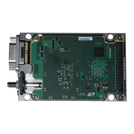
2. OVERVIEWS Physical overview 1. I/O Connector 2. RF Connector 3. Holes (x4) for stack mounting 4. Identification label 5. Internal connector (P2P) Functional overview For complete description of this module, refer to [RD5] or [RD6]. MUT100072E1R3 —... - Page 8 Functional overview GPS — User’s Manual...
-
Page 9: Operation
DAU must be defined in the System Inventory activity (Refer to RD3). System Inventory ▶ Select System Inventory activity. ▶ In the Devices tab, select the GPS module in the DAU (e.g. XMA-1). The GPS module configuration menu appears on the right side. Settings Values Comments Informations... - Page 10 NMEA The receiver produces and interprets messages in accord- ance with NMEA 0183 V3.0 standard. It is possible to send commands to drive the GPS receiver chipset and extract nav- igation data. See NMEA chapter for more details. ◆ ◆...
- Page 11 ◇ Where GPS antenna is not going to suffer sudden changes of position ◇ For smooth flights or flights presenting progressive manoeuvrings ◇ Where the GPS antenna has the visibility of the same set of satellites or changes of its position are done progres- sively NOTICE! Risk of damage to the device! An internal current protection circuitry limit the DC current to 90mA.
-
Page 12: Data Acquisition
▶ Add a digital bus and name it (e.g. GPS_bus). Refer to RD3 to learn how to add a digital bus Note: You must create as many buses as GPS module contained in the DAU. 3.3.2 Digital message ▶ Select a digital bus (e.g. GPS_bus previously created). The line must be underlined. - Page 13 Data Acquisition NMEA Frame Mode A filter can be activated to select one of the seven standard NMEA frames. ▶ Select the frame type you want to extract (NMEA frame types are described in NMEA chapter). NMEA Parameter Mode Fixed extractions are activated to extract predefined parameters on several NMEA frames. With this mode, the user can extract the following information: Parameter name Bits field...
- Page 14 ▶ Once the desired parameter selected, the user can choose the different following options: ■ Refresh Mode Defines the method to output the parameter from GPS module. □ Synchronous: Parameter is sent periodically with a rate of 1Hz. □ Asynchronous: Parameter is sent after its extraction in the corresponding NMEA frame Note: This parameter has impact over the compatibility with output data streams.
- Page 15 Data Acquisition NMEA Extraction Mode This mode allows to extract any field of any NMEA frame type. ▶ Select the NMEA frame type in which you want to extract a field. ■ Refresh Mode See NMEA Parameter Mode ■ Endianness See NMEA Parameter Mode ■...
-
Page 16: Output Data Streams Configuration
▶ Select System Monitoring activity. GPS status are presented in the following screen capture. For more details, refer to GPS MODULE chapter of RD4. The content of a digital bus message is displayed in the Raw data preview window. Only one message can be displayed at a time, if you want to display all messages, use the Quicklook activity. - Page 17 Quicklook ▶ Click on [Stop Acquisition] button to stop recording. Refer to QUICKLOOK chapter of RD3 for more details. MUT100072E1R3 — 02 – 2019...
- Page 18 Quicklook GPS — User’s Manual...
-
Page 19: Nmea Message Format
4. NMEA MESSAGE FORMAT Introduction This chapter contains extracts from the standard describing the NMEA message format and syntax available for the GPS module. For more detail see the website www.nmea.org. Message format All NMEA message and command data consist of ASCII characters (from 20-127 decimal or from HEX 14 to HEX 7E). -
Page 20: Gga - Global Positioning System Fix Data
GGA – Global Positioning System Fix Data GGA – Global Positioning System Fix Data Time, position and fix related data for a GPS receiver. Syntax: $GPGGA,hhmmss.sss,xxmm.ddddd,<N|S>,yyymm.ddddd,<E|W>,v,ss,dd.dd,hhhh.h,M,g.g,M,a.a,xxxx*cs<CR><LF> Example: $GPGGA,084053.39,6016.3051,N,02458.3735,E,0,00,0.0,46.6,M,18.2,M,,*5D Position Parameter Format Designation / Units hhmmss.sss UTC time of the fix. -
Page 21: Gll - Geographic Position - Latitude/Longitude
GLL – Geographic Position – Latitude/Longitude GLL – Geographic Position – Latitude/Longitude Latitude and longitude, UTC time of fix and status. Syntax: $GPGLL,xxmm.ddddd,<N|S>,yyymm.ddddd,<E|W>, hhmmss.dd,S,M*hh<CR><LF> Example: $GPGLL,6016.3073,N,02458.3817,090110.10,A,A*61 Position Parameter Format Designation / Units Latitude coordinate. xx = degrees xxmm.ddddd mm = minutes ddddd = decimal part of minutes <N/S>... -
Page 22: Gsa - Dop And Active Satellites
GSA – DOP and Active Satellites GSA – DOP and Active Satellites GPS receiver operating mode, satellites used in the navigation solution reported by the GGA sentence and DOP val- ues. Syntax: $GPGSA,a,b,xx,xx,xx,xx,xx,xx,xx,xx,xx,xx,xx,xx,pp.pp,hh.hh,vv.vv*cs<CR><LF> Example: $GPGSA,A,3,06,10,15,16,21,25,30,,,,,,2.1,1.2,1.8*38 Position Parameter Format Designation / Units... -
Page 23: Gsv - Satellites In View
GSV – Satellites in view GSV – Satellites in view Number of satellites in view, satellite ID (PRN) numbers, elevation, azimuth and SNR value. The information for four satellites is a maximum per one message, additional messages up to maximum of eight are sent if need. -
Page 24: Rmc - Recommended Minimum Specific Gnss Data
Magnetic variation in degrees, i.e. difference between geometrical and magnetic north direction. <E/W> Letter denoting direction of magnetic variation. Either E = East or W = West. Mode indicator A = autonomous V = data not valid GPS — User’s Manual... -
Page 25: Vtg - Course Over Ground And Ground Speed
VTG – Course Over Ground and Ground Speed VTG – Course Over Ground and Ground Speed Syntax: $GPVTG,h.h,T,m.m,M,s.s,N,d.d,K,M*hh<CR><LF> Example: $GPVTG,202.6,T,208.7,M,0.38,N,0.7,K,A*0D Position Parameter Format Designation / Units Heading in degrees. Letter ‘T’ denoting True heading in degrees Magnetic heading in degrees Letter ‘M’... -
Page 26: Zda - Time And Date
Outputs the current UTC time and date. Unlike other messages, the time output by this message is bound to the GPS chipset’s internal real time clock (RTC) and thus it is updates even when navigation fix is unavailable. The RTC time is maintained also while the module is in sleep mode. -
Page 27: Connectors
5. CONNECTORS Introduction This section provides the complete pin-out for all connectors of the GPS module. Information are not contractual and given for information purposes only. Input/Output connector Signal name Signal name SHLD_GND TX_GPS_RS232 RX_GPS_RS232 CLK10MHZ_TTL_OUT TOP1PPS_TTL_OUT VALID_FIX RESERVED SHLD_GND Note: ◆... - Page 28 RF connector GPS — User’s Manual...
-
Page 29: Troubleshootings
Wrong connection External serial link Pin 2 and 8 malfunction Adapt the DAU configuration to your setup ⇨ GPS data source – page 5 Bad serial configuration Bad antenna connection Verify the RF cable type uses and clamp the plug as recommended in this manual... - Page 30 GPS — User’s Manual...
-
Page 31: Maintenance And Service
The user should refer to the nearest ZODIAC DATA SYSTEMS service representative for assistance in repair and dis- assembly. Maintenance No preventive maintenance is required on the GPS module to ensure optimum overall performance. The GPS module has to be returned to depot for maintenance and repair on following cases: Service Service location: ZODIAC DATA SYSTEMS SAS... - Page 32 Service GPS — User’s Manual...
- Page 33 8. GLOSSARY Acronym Description Amperes American Wire Gauge Binary Coded Decimal Bit Error Rate Configuration Cyclic Redundancy Checking Data Acquisition Unit Decibels Power in decibels relative to carrier Decibel per Hertz dBHz Decibel isotropic Power in decibels relative to 1mW Direct Current Electro-Magnetic Compatibility Firmware Data Base...
- Page 34 Acronym Description Radio Frequency Root Mean Square Recommended Standard 232 (Serial Communications) RS-232 Receive Serial Number. Sample per second Software To Be Defined Transmit Volt Watt GPS — User’s Manual...
- Page 35 Notes: MUT100072E1R3 — 02 – 2019...
- Page 36 5, Avenue des Andes - CS 90101 91978 COURTABOEUF CEDEX - FRANCE Tel.: + 33 - 1 6982 7800 Web: http://www.zodiacaerospace.com | Contact: isite@zodiacaerospace.com...
Need help?
Do you have a question about the GPS and is the answer not in the manual?
Questions and answers