Advertisement
Quick Links
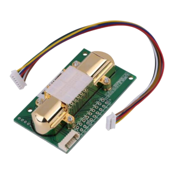
NDIR Infrared Carbon Dioxide Sensor Module
Pin Definition:
Pin name
1,15,17,23
2,3,12,16,22
4,5,21
6,26
8,20
7,9
1,14,18,24
10,13,19,25
Output Method:
PWM output
Assume that the measurement range is 0~2000ppm
CO2 concentration output range
cycle
Model: MH-Z14A
User Manual
Pin description
Power positive (Vin)
Power supply negative (GND)
Analog output (0.4 to 2 V) or (0 to 2.5 V)
HD (zero calibration, low level for more than 7 seconds)
UART (RXD) TTL level data input
UART (TXD) TTL level data output
PWM
NC
0~2000ppm
1004ms±5%
Advertisement

Summary of Contents for Arduino MH-Z14A
- Page 1 NDIR Infrared Carbon Dioxide Sensor Module Model: MH-Z14A User Manual Pin Definition: Pin name Pin description 1,15,17,23 Power positive (Vin) 2,3,12,16,22 Power supply negative (GND) 4,5,21 Analog output (0.4 to 2 V) or (0 to 2.5 V) 6,26 8,20 HD (zero calibration, low level for more than 7 seconds)
- Page 2 High level output at the beginning of the cycle 2ms (theoretical value) Central cycle 1000ms±5% Low-level output at the end of the cycle 2ms (theoretical value) The formula for calculating the current CO2 concentration value is obtained by PWM: Cppm=2000×(TH-2ms)/(TH+TL-4ms) Cppm is the calculated CO2 concentration value in ppm.
- Page 3 Protocol command interface list and meaning 0x86 Read gas concentration value 0x87 Calibration zero (ZERO) 0x88 Calibration span point (SPAN) 0x79 Turn on/off the automatic zero calibration function 0x99 Setting range 0x86-read gas concentration value Send command Byte0 Byte1 Byte2 Byte3 Byte4 Byte5...
- Page 4 Start Reserved Command SPAN high SPAN Check byte 8 digits low 8 value digits 0xFF 0x01 0x88 0xA0/0x00 0x00 0x00 0x00 0x00 Checksum Example: Passing carbon dioxide standard gas 2000ppm, stable for more than 20 minutes; Send command: FF 01 88 07 D0 00 00 00 A0 Perform SPAN point calibration; Note: Calibrate the zero point before calibrating the SPAN value.
- Page 5 3. Add 1:0x78 + 0x01 = 0x79 after inversion. C language checksum routine char getCheckSum(char *packet) char i, checksum; for( i = 1; i < 8; i++) checksum += packet[i]; checksum = 0xff – checksum; checksum += 1; return checksum; Calibration Zero Function: In order to facilitate the user to calibrate the zero point, the sensor has three zero calibration modes: manual zero calibration, command zero calibration, and automatic zero calibration.
- Page 6 The sensor should be calibrated periodically and the calibration period is recommended for no more than 6 months. Do not use the sensor for long periods of time in a dusty environment. In order to ensure the normal operation of the sensor, the supply voltage must be kept in the range of 4.5V~5.5V DC, and the supply current must be no less than 150mA.
Need help?
Do you have a question about the MH-Z14A and is the answer not in the manual?
Questions and answers