
Summary of Contents for DATUM ELECTRONICS 400155
- Page 1 Datum Electronics Datum Universal Interface (DUI) User Guide www.datum-electronics.co.uk | web@datum-electronics.co.uk | +44 (0) 1983 282834...
-
Page 2: Items Supplied
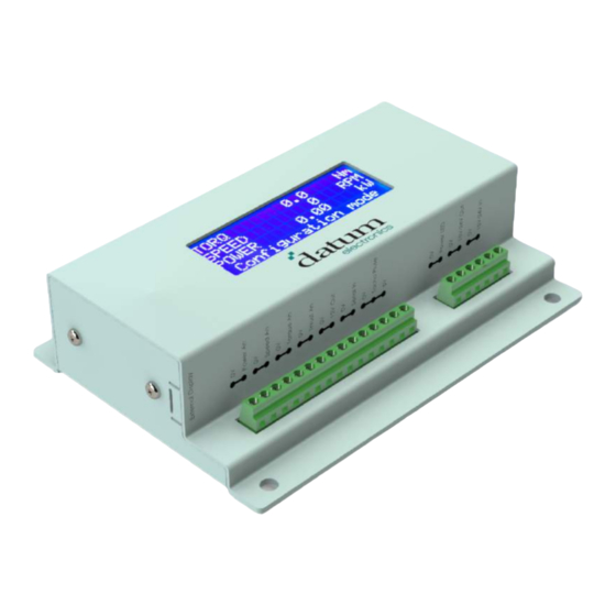
Items Supplied USB Memory Stick with Software and User Guides Datum Universal Interface (DUI) USB A to USB Mini B Lead DUI Power Supply Certificates of Calibration Optional Extra Recharchable Battery www.datum-electronics.co.uk | web@datum-electronics.co.uk | +44 (0) 1983 282834... - Page 3 Familiarisation with Equipment The Datum Universal Interface has a large variety of user configurable options. For a full description of all the user configurable options, how to configure the DUI, and logging functions please see the DUICfg software user guide. Front Display Rear Front Terminal Blocks • The Analogue outputs (Power An, Speed An, Torque An, Thrust An) - user configurable with the DUIcfg software. The 0v is common to all outputs. • 12V Out - copy of the 12V supplied to the torque transducer via the Torque Sensor Serial In • Serial In - copy of the Torque Sensor Serial In located on the rear of the DUI • Tacho Pulse - input allows connection to a tacho independent of the transducer, use of this input requires configuration by Datum Electronics www.datum-electronics.co.uk | web@datum-electronics.co.uk | +44 (0) 1983 282834...
- Page 4 • Power LED – a voltage output for use as an external power status indicator. • 15-24V Out - the input voltage used as an output. It can be used to power an ECR display and is not intended for high current applications. • 15-24V In - an alternative power input usually used with the optional rechargeable battery. It is not recommended to have both this input and the Power In on the rear connected simultaneously. Display During boot-up up the DUI will briefly show the three screens below. The second screen shows the firmware version (v2.4.0 in the example shown), Serial input setting (shown set to connect to a 425 series transducer) and, Serial output setting. The third screen shows the ethernet settings. After boot-up the DUI will display Torque, Speed in RPM and, Power on the first three lines. The fourth line shows the transducer connection status. The number of decimal places displayed (for torque, speed and, power) and, units displayed (for torque and power) are user configurable. With no connection to a transducer the display will alternate between STATUS no input and Sample per sec 0, as below: www.datum-electronics.co.uk | web@datum-electronics.co.uk | +44 (0) 1983 282834...
- Page 5 When correctly connected to a transducer the display will alternate between STATUS OK and Sample per sec 100 (for a 425 series transducer), as below: If the display is showing no input with a transducer connected please refer to transducer user guide FAQ. Rear • Torque Sensor Serial In – a 9 pin male D connector to connect to the Datum Electronics Torque transducer. • Zero Reset – when first connected all transducers have a small offset with 0 torque applied. Hold this button in for 3 seconds, observing the countdown on the display, to remove the offset. • Ethernet socket – user configurable output for remote PC logging. • USB Type A socket – User configurable logging to a USB memory stick. • USB Mini B socket -connects to the DUIcfg software for PC logging and user configuration of other outputs. • Power In – power socket for used with the power supply provided only. It is not recommended to have both this input and the 15 – 24V In on the front connected simultaneously. • Serial Out – user configurable 9 pin female serial output. This output can be configured to RS232, RS485 or, for firmware version 2.5.1 and above, MODBUS. www.datum-electronics.co.uk | web@datum-electronics.co.uk | +44 (0) 1983 282834...
-
Page 6: Typical Setup
Typical Set Up In the typical set-up shown below the DUI is connected to the PC for logging the results or configuring the DUI. www.datum-electronics.co.uk | web@datum-electronics.co.uk | +44 (0) 1983 282834... -
Page 7: Certificate Of Calibration
Certificate of Calibration 1. Customer and Job details 2. Details of DUI calibrated, including firmware version and serial number 3. Equipment used to calibrate the DUI 4. Details of the transducer the DUI has been configured to work with 5. Analogue output settings 6. Calibration settings this describes the relationship between the strain gauge output and the torque, this should match the calibration certificate of the transducer in section 4 7. Operative and date of calibration. www.datum-electronics.co.uk | web@datum-electronics.co.uk | +44 (0) 1983 282834... - Page 8 Certificate of Calibration www.datum-electronics.co.uk | web@datum-electronics.co.uk | +44 (0) 1983 282834...
-
Page 9: Mounting Overview
Mounting Overview The DUI can be mounted using the four 6mm holes. Please see below for dimensions. Document: 1066 Issue: 1 Date: 22/10/2018 www.datum-electronics.co.uk | web@datum-electronics.co.uk | +44 (0) 1983 282834... - Page 10 Datum Eectronics Limited Datum World HQ Castle Street East Cowes Isle of Wight PO32 6EZ United Kingdom Telephone: +44 (0) 1983 282834 Fax: +44 (0) 1983 282835 Email: support@datum-electronics.co.uk Website: www.datum-electronics.co.uk www.datum-electronics.co.uk | web@datum-electronics.co.uk | +44 (0) 1983 282834...
Need help?
Do you have a question about the 400155 and is the answer not in the manual?
Questions and answers