
Summary of Contents for Sierra TV-10
-
Page 1: Cover
TV-10 Dry Vacuum System 2022 USER MANUAL/Installation Instructions 1953 W. Gulf To Lake Hwy, Lecanto, FL 34461 Phone: 352-527-1975 FAX: 352-513-4801 www.Dentalvacuums.com sierradentalequipment@outlook.com... -
Page 2: Table Of Contents
TABLE OF CONTENTS Cover Congratulations Customer support Warranty Policy Safety Sub Assemblies What’s Included Specifications -Site requirements -Product Specifications -Tank Specifications -Chassis Specifications System Layout Installation Operation Maintenance Troubleshooting Accessories Congratulations! On the Purchase of your TRU-VAC dry vacuum system. This state-of-the-art dry vacuum is a very powerful, high volume, efficient system. -
Page 3: Customer Support
“We are happy to help you with any questions or concerns you may have about your equipment” Contact Us at 352-527-1975. We’re here to help! sierradentalequipment@outlook.com DentalVacuums.com Look for us… on social media! Sierra Dental Equipment Inc. 1953 W. Gulf to Lake Hwy Lecanto, FL 34461... -
Page 4: Warranty Policy
Sierra Dental Equipment Limited Warranty Warranty for the TRU-VAC Dry Vacuum System is limited to the original purchaser of the unit. Sierra Dental Equipment is only obligated under this warranty to the repair or replacement of defective parts or materials. The defect(s) must be reported to Sierra Dental Equipment within the valid warranty period. -
Page 5: Safety
SAFETY Use of the TRU-VAC not in compliance with the instructions specified in this manual may result in permanent failure / voided warranty of the unit. WARNING To prevent fire or electrical shock, do not expose this unit to rain or moisture, excessive heat or improper ventilation. -
Page 6: Sub Assemblies
SUB ASSEMBLIES Low Voltage Control Box Vortex Action Separator Tank Motor Assembly... -
Page 7: What's Included
X1 Vacuum Relief Valve/Tee................(1 ½" Male Slip x 1 ½" Female Slip) X1 Filter........................(1 ½" fpt x 1 ½" male slip) k) X1 TV-10………………………...…..……………………………………..….……………….…….USER MANUAL X1 Warranty Card…………….….………………………………….…..……(Fill Out And Return within 30 days) 1 ¼" fpt x 2" fpt galv. -
Page 8: Specifications
SPECIFICATIONS SITE REQUIREMENTS Specification Description (TV-10) 15 Amp Circuit breaker rating (230 Volts) Minimum 14 Gauge wire size 2” trunk - 1 ½’ branch Vacuum piping (PVC) 2” High temperature flex hose, 2" SCH. 80 Gray PVC, 2" galvanized, 2" copper, 3"... -
Page 9: Product Specifications
SPECIFICATIONS PRODUCT SPECIFICATIONS Specification Description (TV-10) Voltage 230 V AC Operating load 8.3 Amps Start-up load 14 Amps Frequency 50 – 60 Hz Low voltage remote 24 V AC Max operators 5 users (5 HVE) or (10 SE) Tank capacity... -
Page 10: Tank Specifications
SPECIFICATIONS TANK SPECIFICATIONS TANK Weight Length Width Height Capacity V.A.S. 43 lbs. 15” 17” 40” 12 Gal. 40" 15" 17"... -
Page 11: Chassis Specifications
SPECIFICATIONS CHASSIS SPECIFICATIONS CHASSIS Weight Length Width Height 94 lbs. 20 ½” 20 ¼” 19 ½" TV-10 19 ½" (including rubber feet, not pictured) 20 ¼ " 20 ½"... -
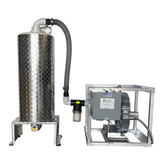
Page 12: System Layout
SYSTEM LAYOUT Vacuum gauge Vortex action From separator tank operatories Motor assembly Exhaust Inlet vacuum Check valve filter cartridge drain 1 ½” PVC 24-volt Power cord remote wires V AC Low voltage 1.74 HP control box pump... -
Page 13: Installation
INSTALLATION Tank placement is all according to your specific location requirements. -You can place your (VAS) tank beside the motor assembly (Figure A) -You can stack the tank on top of the chassis(Figure B). -You have the option to install the intake filter on top of the tank (Figure C.) The VAS tank can be installed in an alternate area of the practice if necessary. - Page 14 INSTALLATION Figure 1. Find a location that fits the required site specification. 2. Wherever you plan to mount motor assembly, be sure that the 230 volt power source is readily available. 3. Place your motor assembly on the ground, if the (VAS) tank is going to be mounted on top of the motor chassis do so now.
- Page 15 INSTALLATION 6. Connect the pre-existing operatory lines to the tank. (Fig. 4) Unless you plan to Figure run all new lines. 7. We provide a 2" FPT steel pipe exhaust. (Fig. 5) Route exhaust with this same material or similar high temp flex pipe to an outside vent.
- Page 16 INSTALLATION 9. Route and connect the motor assembly power cord to a dedicated *230 volt source. Maximum circuit breaker rating: 15 AMPS per motor. *Box supplied by customer. 230V Green = Ground Blue = L1 Red = L2 *Connections are to be made by a certified electrician* 10.
-
Page 17: Operation
OPERATION Green light indicates 24 volts ON Figure 7 (Fig.7) If the system will not turn on. Always check the circuit breaker (Fig. 8) Figure 8 Figure 9 For use with an alternate remote switch, the remote switch is wired correctly to the 24 volt remote wires. This Feature will allow you to control your system with a remote switch (Fig 9). -
Page 18: Maintenance
DO NOT ATTEMPT TO ADJUST THE VACUUM RELIEF VALVE The vacuum relief valve is a preset part @ 8" HG, Sierra Dental Equipment Inc. has set the standard for this valve according to many variables. Adjusting the vacuum relief valve, will void your warranty. -
Page 19: Troubleshooting
Cogged amalgam Seperator, contact Sierra Dental 230 V circuit breaker is Turn the circuit breaker Pump does Remote switch is OFF or Make sure remote switch not run not correctly connected is ON, call Sierra Dental Electrical issue Call Sierra Dental... -
Page 20: Accessories
This kit comes equipped with 5' of high temperature flexible hose and all the fittings you'll need to ensure set up is a breeze! This accessory is compatible with the TV-10 and TV- 12. We also have a model available for the TV- 20 and TV-22. - Page 21 # Chairs: _______ ** DO NOT adjust vacuum relief valve unless # of HVEs: _________ specifically directed by Sierra Dental. This WILL void # of SEs: ___________ your warranty. MUST be at 8.5 HG" Sign Here to Verify Steps above for WARRANTY VALIDATION:...
Need help?
Do you have a question about the TV-10 and is the answer not in the manual?
Questions and answers