Table of Contents
Advertisement
Quick Links
Specifications Information and Repair Parts Manual
Please read and save this Repair Parts Manual. Read this manual and the General Operating Instructions carefully before attempting to assemble,
install, operate or maintain the product described. Protect yourself and others by observing all safety information. The Safety Instructions are contained
in the General Operating Instructions. Failure to comply with the safety instructions accompanying this product could result in personal injury and/or
property damage! Retain instructions for future reference. AMT reserves the right to discontinue any model or change specifications at any time without
incurring any obligation.
©2019 AMT Pump Company, A Subsidiary of The Gorman-Rupp Company, All Rights Reserved.
Periodic maintenance and inspection is required on all pumps to insure proper operation. Unit must be clear of debris and sediment. Inspect for leaks and loose bolts. Failure
to do so voids warranty.
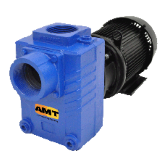
3-Inch Solids-Handling
Pedestal Pump
Refer to pump manual 1808-635-00 for General Operating and Safety Instructions.
DESCRIPTION
These high capacity, heavy-duty self-priming (to 20 ft. lift) pumps, are designed for direct coupling drive or pulley drive. Each pump is equipped with a
clog-resistant cast iron impeller capable of handling solids up to ¾" diameter. Pump is designed for operations involving irrigation and dewatering of
excavations, basements, etc. Handles liquids from 40̊ to 180̊ F (4̊ to 82̊ C). For use with nonflammable, non-abrasive liquids compatible with pump
component materials.
SPECIFICATIONS
Suction Inlet....................................................................3" NPT
Discharge Outlet..............................................................3" NPT
Shaft Diameter....................................................................1 ⅛"
Keyway...............................................................1/4 x 1/8 x 2 ¼"
Dimensions
(Overall).............................................L 20 ½" x W 10 ½" x H 13"
Weight............................................................................85 lbs.
Seals...........................3391-99 – Buna-N with carbon/ceramic faces
..................................3391-V9 – Viton with carbon/ceramic faces
Performance Chart
Pump
Elec. Motor*
Speed
Motor
RPM
HP
RPM
PD
3.0"
1725
1 ½
1800
2.5"
1 ½
3600
5.5"
2800
5
1800
3.5"
5 ½
3600
7.0"
3450
7 ½
1800
3.5"
7 ½
3600
Note: RPM listed are synchronous, actual RPM is very close to 3450 for 3600 and 1725 for 1800.
(*) Minimum electric motor HP required.
3391-252-00
Sheave
Pump
No. of
PD
Grooves
10'
3.0"
1
6,600
5.0"
1
3.5"
2
13,500
4.5"
2
3.5"
2
17,100
3.5"
2
MAINTENANCE
Make certain that unit is disconnected from power source before
attempting to service or remove any components! If power disconnect
is out-of-sight, lock it in open position and tag to prevent application
power.
MECHANICAL SEAL REPLACEMENT
Refer to Figures 1 and 2
IMPORTANT: Always replace seal seat (Ref. No. 7), seal head (Ref.
No. 6), and shaft sleeve (Ref. No. 5) to insure proper mating of
mechanical seal components!
1.
Remove pump casing (Ref. No. 2), casing seal (Ref. No. 8)
and impeller (Ref. No. 3)
NOTE: Mechanical shaft seal consists of 2 faces, one stationary (seat)
and other rotating (head). When removing seal refer to Figure 2, and
carefully note position of seal faces and how they fit one to the other.
Seat is installed in adapter (Ref. No. 9) and head (located around
shaft) rides up against seat. The purpose of rubber components is to
seal parts to housings and shaft and/or shaft sleeve. The purpose of
stainless steel spring is to maintain pressure of carbon face to ceramic
face.
GPM at Total Head in Feet
20'
30'
40'
50'
−
−
−
3,120
12,000
10,140
8,160
5,280
15,900
14,700
13,200
11,460
1
3391-99 and 3391-V9
60'
70'
80'
90'
−
−
−
−
−
−
−
840
9,900
7,800
5,100
1,500
Max
Head
23 ft.
61 ft.
92 ft.
4/2019
Advertisement
Table of Contents

Related Manuals for GORMAN-RUPP AMT 3391-V9


Summary of Contents for GORMAN-RUPP AMT 3391-V9
- Page 1 ©2019 AMT Pump Company, A Subsidiary of The Gorman-Rupp Company, All Rights Reserved. Periodic maintenance and inspection is required on all pumps to insure proper operation. Unit must be clear of debris and sediment. Inspect for leaks and loose bolts. Failure to do so voids warranty.
- Page 2 3391-99 and 3391-V9 Specifications Information and Repair Parts Manual 3-Inch Solids-Handling Pedestal Pump MAINTENANCE (Continued) Remove shaft sleeve with sea head on it. Separate seal head from sleeve. Remove adapter from bearing housing (Ref. No. 12), then using two screwdrivers or other suitable tools, remove seal seat from adapter.
- Page 3 3391-99 and 3391-V9 Specifications Information and Repair Parts Manual For Repair Parts contact dealer where pump was purchased. Please provide following information: -Model Number -Serial Number (if any) Part description and number as shown in parts list Figure 2 – Repair Parts Illustration 3391-252-00 4/2019...
- Page 4 3391-99 and 3391-V9 Specifications Information and Repair Parts Manual Repair Parts List Ref. Part Number for Models: Description 3391-99 3391-V9 Qty. 3/4" NPT Drain Plug Incl. w/ Ref. 2 Incl. w/ Ref. 2 Casing Kit with Buna Flapper 3391-001-95 Casing Kit with Viton Flapper 3270-002-95 (includes Ref.
- Page 5 3391-99 and 3391-V9 Specifications Information and Repair Parts Manual NOTES: 3391-252-00 4/2019...
- Page 6 3391-99 and 3391-V9 Specifications Information and Repair Parts Manual NOTES: 3391-252-00 4/2019...
- Page 7 3391-99 and 3391-V9 Specifications Information and Repair Parts Manual 3391-252-00 4/2019...
- Page 8 3391-99 and 3391-V9 Specifications Information and Repair Parts Manual www.amtpump.com 3391-252-00 4/2019...
Need help?
Do you have a question about the AMT 3391-V9 and is the answer not in the manual?
Questions and answers