Advertisement
Quick Links
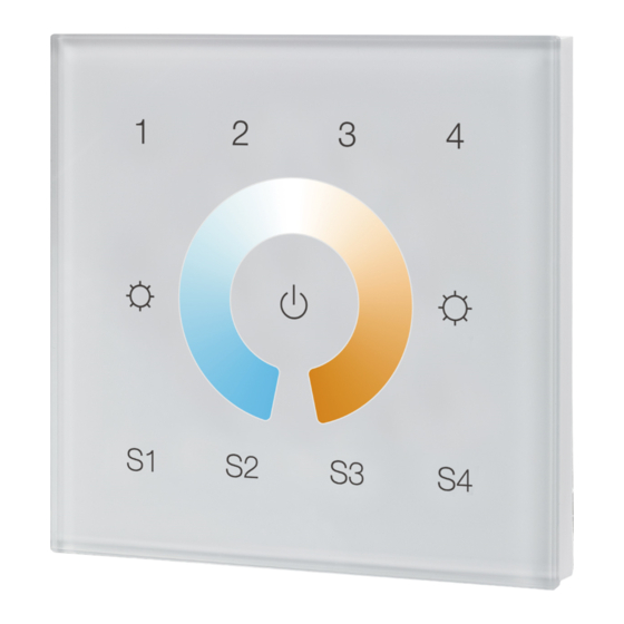
Z-Wave Wall Controller SR-ZV9002T4-CCT-RU
Safety & Warnings
•
DO NOT install with power applied to device.
• DO NOT expose the device to moisture.
Quick Start
How to install:
• Step 1: turn on your wall controller.
• Step 2: activate inclusion mode on your Z-Wave controller.
• Step 3: activate inclusion mode of your wall controller by pressing the
"inclusion/exclusion" button or long press "ALL ON/OFF" button over 3 seconds.
Product Description
The Wall controller is a Security Enabled Z-Wave Plus device that can both control other
Z-Wave devices and activate scenes in Gateways. The wall controller can be included
and operated in any Z-Wave network with other Z-Wave certified devices from other
manufacturers and/or other applications. All non‐battery operated nodes within the
network will act as repeaters regardless of vendor to increase reliability of the network.
Although it is controlling other devices, the device cannot act as Z-Wave network
controller (primary or secondary), so a security enabled controller is needed for take full
advantage of all functionally for the device. It also supports the Over The Air (OTA)
feature for the product's firmware upgrade.
The wall controller has following functions:
1. Control of groups of other Z-Wave devices using 'ON', 'OFF', Dim and Color Control
commands.
2. Activation of scenes in Gateways.
The encryption modes that the wall controller supports are S0, S2 Unauthenticated.
When the wall controller is being included into a Z-Wave network, you can use your
primary controller/gateway to enable one encryption mode or disable encryption. (The
primary controller/gateway shall support encryption mode configuration).
Product Data
Z-Wave Frequency
Power Supply
Power Consumption
Operating temperature
Relative humidity
869.0 MHz (RU)
100-240VAC, 50/60Hz
< 0.5W
0 to 40°C
8% to 80%
Advertisement

Summary of Contents for Z-Wave Alliance SR-ZV9002T4-CCT-RU
- Page 1 Z-Wave Wall Controller SR-ZV9002T4-CCT-RU Safety & Warnings • DO NOT install with power applied to device. • DO NOT expose the device to moisture. Quick Start How to install: • Step 1: turn on your wall controller. • Step 2: activate inclusion mode on your Z-Wave controller.
- Page 2 0% PWM1 + 100% PWM2 100% PWM1 + 0% PWM2 Save and recall 4 scenes Front side 60.3 mm 52.0 mm 19.4 mm Z-Wave Controller SR-ZV9002T4-CCT-RU PRI: Uin=100-240VAC Inclusion/Exclusion” Button Iin=15mA MAX Out=Z-Wave Signal AC Power input Back side Installation Guide Please read carefully the enclosed user manual before installation of wall controller, in order to ensure an error-free functioning.
- Page 3 circular European wall boxes with 60mm diameter. ATTENTION: Only authorized technicians under consideration of the country specific installation guidelines/norms may do works with 100-240V mains power. Prior to the assembly of the product, the voltage network has to be switched OFF and ensured against re-switching.
- Page 4 the primary controller/gateway is missing or otherwise inoperable. How to check whether the wall controller already included to a network Operate any button to check if there is indication from the LED indicator, and no LED indication means the wall controller does not belong to any network. If the wall controller already belongs to a network, follow the exclusion process before including it in your network.
- Page 5 direct control of associated devices using Scene Activation Set, Scene ID = 0x10 / 0x20 / 0x30 / 0x40. 3. Press and hold down Scene button Launch 1 S1/S2/S3/S4, direct control of associated devices using Scene Conf Set, Scene ID = 0x10 / 0x20 / 0x30 / 0x40.
- Page 6 Set and unset associations: (Note: All association information will be cleared automatically once the wall controller is excluded from a network.) Associations can be assigned and remove either via Z-Wave commands or using the device itself. 1. Set association by operating primary controller/gateway to send packets to the wall controller: The primary controller/gateway sends packets to the wall controller using “Command Class ASSOCIATION”...
- Page 7 50% PWM1 +50% PWM2 4 Groups Color Wheel for adjusting relative brightness ALL ON/OFF button, broadcast to turn on/off all between PWM1 and PWM2 Decrease whole brightness Increase whole brightness 0% PWM1 + 100% PWM2 100% PWM1 + 0% PWM2 Save and recall 4 scenes Choose the objects you would like to control: •...
- Page 8 Node Information Frame The Node Information Frame is the business card of a Z-Wave device. It contains information about the device type and the technical capabilities. The inclusion and exclusion of the device is confirmed by sending out a Node Information Frame. Beside this it may be needed for certain network operations to send out a Node Information Frame.
- Page 9 Manufacturer Specific Parameter Value (hex) Manufacturer ID 0x0330 Product Type ID 0x031A Product ID 0xa103 SUPPORTED COMMAND CLASS SUPPORTED COMMAND CLASS Support S2 Node Info COMMAND_CLASS_ZWAVEPLUS_INFO COMMAND_CLASS_SECURITY COMMAND_CLASS_SECURITY_2 COMMAND_CLASS_TRANSPORT_SERVICE COMMAND_CLASS_SUPERVISION COMMAND_CLASS_SWITCH_MULTILEVEL COMMAND_CLASS_SWITCH_COLOR COMMAND_CLASS_SCENE_ACTIVATION COMMAND_CLASS_SCENE_ACTUATOR_CONF COMMAND_CLASS_MANUFACTURER_SPECIFIC COMMAND_CLASS_VERSION COMMAND_CLASS_ASSOCIATION_GRP_INFO COMMAND_CLASS_MULTICHANNEL_ASSOCIATION COMMAND_CLASS_CENTRAL_SCENE COMMAND_CLASS_ASSOCIATION COMMAND_CLASS_POWERLEVEL COMMAND_CLASS_DEVICE_RESET_LOCALLY COMMAND_CLASS_FIRMWARE_UPDATE_MD...
-
Page 10: Wiring Diagram
Wiring diagram Z-Wave Controller SR-ZV9002T4-CCT-EU PRI: Uin=100-240VAC Iin=15mA MAX Out=Z-Wave Signal AC Power 50/60Hz AC 100-240V Installation...
Need help?
Do you have a question about the SR-ZV9002T4-CCT-RU and is the answer not in the manual?
Questions and answers