Table of Contents
Advertisement
Quick Links
Advertisement
Table of Contents

Related Manuals for Daruifuno DEC79

Summary of Contents for Daruifuno DEC79
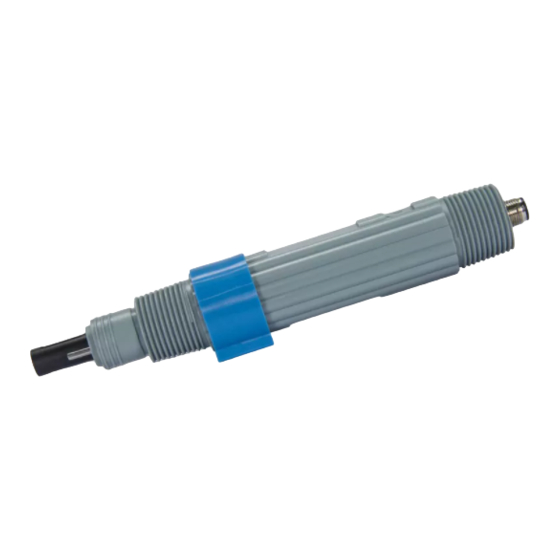
- Page 1 Daruifuno Conductivity Sensor Basic User Manual Model: DEC79 Version 1.0...
-
Page 3: Table Of Contents
Contents Chapter 1 Specification..................1 Chapter 2 Basic Information.................2 2.1 Security Information..............2 2.2 Overview..................2 2.3 Dimension..................2 Chapter 3 Installation..................3 3.1 Sensor Installation................3 3.2 Sensor Wiring..................4 Chapter 4 Use....................5 4.1 Communication..................5 4.2 Read Measurements.................5 4.3 Sensor Calibration................5 4.3.1 Two Points Calibration................5 4.3.2 Multi-point Calibration..............6 4.3.3 Temperature Correction..............6 4.4.4 Reset Calibration................6 Chapter 5 Maintenance..................7... - Page 4 Guarantee Our company seriously warrants each of the instrument for one year (12 months) from the specific date of delivery. Consumables and consumable parts in the equipment are not covered by the warranty. The terms of this warranty shall not apply if damage to the instrument occurs beyond the warranty period, or in the opinion of the company, the breakage or destruction of the instrument is due to improper use, lack of maintenance, improper installation, improper modification, abnormal environmental conditions, etc.
-
Page 5: Chapter 1 Specification
Specification Chapter 1 Specification Product specifications are subject to change without notice. Measuring Principle Graphite two electrode measurement principle 0~20uS/cm, 20~200uS/cm, 200~2000uS/cm, 2~10mS/cm Measuring Range 0.0~50.0℃ 0.01uS/cm 、0. 1uS/cm 、1uS/cm Resolution 0 1℃ ±1.0%FS Accuracy Temp Compensation 0~50°C, NTC automatic or manual Deviation correction, factor correction, Calibration Method... -
Page 6: Chapter 2 Basic Information
Basic Information Chapter 2 Basic Information 2.1 Security Information Please read this manual completely before unpacking, installing and operating this equipment. Pay special attention to all precautions. Otherwise, it may cause serious personal injury to the operator or damage the equipment. 2.2 Overview The sensor is based on the principle of two-electrode measurement. -
Page 7: Chapter 3 Installation
Installation Chapter 3 Installation 3.1 Sensor Installation Refer to the pictures in this section to install and fix the sensor. To ensure that the sensor can measure safely and accurately, the following conditions must be met during installation: In pipeline installation, the sensor should be installed at a low position in the pipeline, with a stable flow rate and not prone to air bubbles;... -
Page 8: Sensor Wiring
Sensor Wiring Overflow Outlet water intake Figure 3 Schematic diagram of installation of five-parameter flow cell 1-Flow cell 4-pH sensor fixed connection cover 2-Flow cell cover 5-DO sensor fixed connection cover 3-Turbidity sensor fixed connection cover 6-Conductivity sensor fixed connection cover 3.2 Sensor Wiring The sensor is correctly connected as defined in the table below. -
Page 9: Chapter 4 Use
Chapter 4 Use 4.1 Communication The sensor communication is RS485 Modbus-RTU, please refer to Modbus related protocol description for specific communication protocol. The default communication parameters of the sensor are: communication address=17, baud rate=9600, parity bit=none, stop bit=1 bit, the information parameters can be modified by referring to the register description in Appendix A 4.2 Read Measurements Sensor measurements can be read by connecting the meter or using other Modbus master... -
Page 10: Multi-Point Calibration
4.3.2 Multi-point Calibration Multi-point calibration requires preparation of four standard solutions: 84uS, 146uS, 1413uS, and 12880uS. The calibration process is as follows: Use deionized water to clean the electrode and absorb the residual moisture with filter paper. Place the electrode in dry air and wait for the measured value to stabilize. Use the 16 function code to write a value of 0 to the 23 register;... -
Page 11: Chapter 5 Maintenance
Maintenance Chapter 5 Maintenance The sensor contains precision photoelectric components. Please make sure that the sensor will not be subject to any strong mechanical impact during use. There are no user maintenance parts inside the sensor. 5.1 Maintenance Cycle Maintenance work Maintenance frequency Visual inspection Every month... -
Page 13: Appendix A Modbus Register Information
Appendix Appendix A Modbus Register Information Access Function Item Register Data Type Length Description Type Code Unsigned Non-zero means the sensor is State Read integer performing calibration Conductivity Floating point Read Output value unit:uS/cm measure Temperature Temperature measurement value, Floating point Read unit: ℃... - Page 14 Appendix Access Function Item Register Data Type Length Description Type Code Zero point CAL Floating point Write 03/16 Write 0 to perform zero point calibration Write the calibration solution value to Point 1st CAL Floating point Read/write 03/16 start calibration, 84uS/cm Write the calibration solution value to Point 2nd CAL Floating point...
- Page 16 Delfino Environmental Technology Co., Ltd. www.daruifuno.com info@daruifuno.com...
Need help?
Do you have a question about the DEC79 and is the answer not in the manual?
Questions and answers