Table of Contents
Advertisement
Quick Links
AIR CONDITIONER
OPTIONAL PARTS
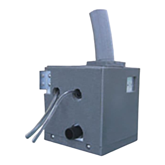
DRAIN PUMP UNIT
INSTALLATION MANUAL
For authorized service personnel only.
UTZ-PX1NBA
Contents
1. SAFETY PRECAUTIONS .............................................. 1
2. MAIN UNIT AND ACCESSORIES .................................. 1
3. DIMENSION ................................................................... 2
4. LOCATION ..................................................................... 2
5. INSTALLATION PROCEDURES .................................... 3
6. DRAINAGE CONSTRUCTION ...................................... 4
7. ELECTRICAL WIRING ................................................... 5
8. TEST RUNNING ............................................................ 7
9. INSULATION OPERATION ............................................ 8
10. MAINTENANCE DURING OFF SEASON ...................... 8
11. FINAL CHECKS AFTER CONSTRUCTION................... 8
1. SAFETY PRECAUTIONS
This mark indicates procedures which, if
improperly performed, are most likely to
DANGER
result in the death of or serious injury to the
user or service personnel.
Never touch electrical components immediately after the
power supply has been turned off. Electrical shock may oc-
cur. After turning off the power, always wait 5 minutes or more
before touching electrical components.
This mark indicates procedures which, if
improperly performed, might lead to the
WARNING
death or serious injury of the user.
For the air conditioner to operate satisfactorily, install as outlined
in this installation manual.
Connect the indoor unit and drain pump unit with the air
conditioner hose and cords available standards parts. This
installation manual describes the correct connections using
the installation set available from our standard parts.
Installation work must be performed in accordance with national
wiring standards by authorized personnel only.
Do not turn on the power until all installation work is com-
plete.
This mark indicates procedures which, if
improperly performed, might possibly result
CAUTION
in personal harm to the user, or damage to
property.
Install a drain pump unit to each indoor unit. If 1 drain pump unit
is connected to multiple indoor units, leakage may occur.
Do not exert excess pressure, for example when holding the
supplied drain hose. Otherwise the drain hose may come off
and cause injuries.
Do not turn off the power supply for 5 minutes after the opera-
tion has been stopped. Otherwise the remaining drain water
may not be drained and leakage may occur.
If leakage occurs from the interior of the indoor unit or drain
pump unit during operation of the air-conditioner, stop the
operation immediately. The drain outlet may be jammed and
the safety circuit may not be working properly. Please contact
your dealer.
2. MAIN UNIT AND ACCESSORIES
• The following installation parts are furnished. Use them as
required.
* The parts numbers are the same as those indicated in the
diagrams.
Name and shape
Q'ty
Drain pump unit
1
Installation manual
1
1 Hanger
1
PART NO. 9378754027-04
Name and shape
8 Hose band (Big)
9 Joint hose
0 Special nut A
(Large fl ange)
A Special nut B
(Small fl ange)
Q'ty
1
1
1
1
En-1
Advertisement
Table of Contents

Related Manuals for Fujitsu UTZ-PX1NBA


Summary of Contents for Fujitsu UTZ-PX1NBA
- Page 1 AIR CONDITIONER PART NO. 9378754027-04 OPTIONAL PARTS DRAIN PUMP UNIT INSTALLATION MANUAL For authorized service personnel only. UTZ-PX1NBA This mark indicates procedures which, if improperly performed, might possibly result Contents CAUTION in personal harm to the user, or damage to property.
- Page 2 Name and shape Q’ty Name and shape Q’ty Top side Unit: mm (in.) (6-1/2) 2 Bracket B Insulation 1177 (46-11/32) (hose) 1135 (44-11/16) 3 Tapping screw C Cable tie holder 4 Insulation D Cable tie 40×26 mm (1-9/16×1 in.) 178 (7) Back side Connected drain pipe (locally arranged) Inner diameter 25mm (1 in.)/Outer 32mm...
- Page 3 (4) Paste the insulation so that the nut and the exposed part of 5. INSTALLATION PROCEDURES the bracket are covered. 1. Installing drain pump unit 6 Insulation 35×35 mm (1) Use the tapping screw to install the hanger and bracket to the (1-3/8 ×1-3/8 in.) drain pump unit.
- Page 4 2. Leveling Example of Wrong Construction CAUTION CAUTION • Install the indoor unit and drain pump unit within the accept- Do not install the pipe’s connection part upward. Remaining able gradient range. Otherwise, the safety device will not work drain water in the pipe may cause leakage. properly and leakage may occur.
- Page 5 1.5 to 2m gap (60 to 78 in.) (2) The position to insert the connector is different depending on the indoor unit. For wiring other than the drain pump unit, follow the Installation Supporter Locally ar- manual of the indoor unit. ranged pipe For U.S.A.
- Page 6 For Others (Type 2) • Operation of mounting position “b” Thread the Cable tie through the cable clamp of the indoor unit and tighten both the fl oat switch wire and the remote controller cable etc. (The type and number of wire vary depending on the model) D Cable tie Tapping screw Float switch wire...
- Page 7 [BOARD TYPE D] Thin tube FLOAT SW CNA05 Thick tube (Red) E Wire clamp 9 Joint hose Refrigerant pipe WARNING Do not allow the tube to come into contact with the refrigerant pipe or joint hose as it may cause short circuit. D.PUMP CN106 8.
- Page 8 10. MAINTENANCE DURING OFF SEASON 9. INSULATION OPERATION • Clean the drain pump unit after every air conditioning season. CAUTION • Remove the screw and open the bottom lid to remove the drain Be sure to install the insulation. Otherwise water leakage pan.
Need help?
Do you have a question about the UTZ-PX1NBA and is the answer not in the manual?
Questions and answers