
Summary of Contents for Intelligent Lighting Controls Light Master
- Page 1 U S E R G U I D E Version 1C 9/20/00 INTELLIGENT LIGHTING CONTROLS, INC. 5229 Edina Industrial Boulevard Minneapolis. Minnesota 55439 Phone 952 829 1900 FAX 952 829 1901 1-800-922-8004...
- Page 3 The Light Master Programmable Contactor is a microprocessor-based programmable lighting controller. You can program each of the controller inputs to control any or all of the relay out- puts. The Light Master is UL and FCC approved for commercial and residential applications. Structure CPU I/O Board –...
- Page 4 2.6 Troubleshooting................2.6.1 Controller Will Not Power-Up ..........2.6.2 Lighting Relay(s) Will Not Function........2.6.3 Switch Input Will Not Function..........2.6.4 Timers Will Not Function Properly ........2.6.5 Entire I/O Board(s) Doesn’t Work ........Light Master User Manual Version 1C 9/20/00...
-
Page 5: Table Of Contents
4.2.2 Map the Switch to the Relays ..........4.3 Wire and Program a Photocell Controller Contact to Control Relays ................4.3.1 Define the Photocell Contact..........4.3.2 Map the Photocell Contact to the Relays ......Light Master User Manual Version 1C 9/20/00... - Page 6 4.5.2 Map the BAS System Contact to the Relays..... 4-11 4.6 Control Relays by Time of Day Schedules ........4-12 4.6.1 Set the Light Master Clock to Current Date and Time ..4-13 4.6.2 Define the Timers ..............4-14 4.6.3 Map the Timer to the Relays ..........
- Page 7 Section 1 Controller Description LIGHT MASTER WED 10/30/99 07:50:54 AM EDIT (c) 99 ILC Light Master User Manual Version 1C 9/20/00...
- Page 8 1.1.1 Enclosure................1.1.2 Transformer ................1.1.3 CPU I/O Board............... 1.1.4 Additional I/O Boards............1.1.5 Programming Module ............1.1.6 Lighting Relays............... 1.2 I/O Options ..................1.2.1 Telephone Add-On Module ..........1.2.2 PC Add-On Module ............. Light Master User Manual Version 1C 9/20/00...
- Page 9 Controller. Light Master to control lighting relays in response to switch signals sensed by its inputs and/or by time-based scheduling. The Light Master is UL approved and FCC certified for both commercial and residential applications. Light Master User Manual 1 - 1...
- Page 10 8, 16, 24, 32, 40 and 48 inputs, out- • control transformer puts, and lighting relays. See (Table 1-1.) The • CPU I/O board Light Master is shipped to the job-site as a • additional I/O boards complete assembly. (See Figure 1-1, which illustrates a Light Master 8.) •...
- Page 11 Controller Description 1.1.3 CPU I/O Board – (See Figure 1.2.) The • Switch Inputs – The Light Master is designed CPU board provides the controller’s intelli- to accomplish a wide variety of switch gence and memory and the first eight (8) of input types.
- Page 12 Figure 5 – The electromagnet and the permanent magnets Figure 4 – The electromagnet and the permanent magnets combine to switch the contacts to the open position. combine to switch the contacts to the closed position. Light Master User Manual 1 - 4 Version 1C 9/20/00...
- Page 13 Control transformer Grounding Lug Enclosure CPU I/O board Lighting relays ORANGE ORANGE STATUS BLACK (OFF) Programming module RED (ON) BLUE (COM) Relay termination detail Figure 1.1 – Light Master 8 Controller Light Master User Manual 1 - 5 Version 1C 9/20/00...
- Page 14 Switch input Data to Relay output Pilot Power to status LEDs next board status LEDs next board Status terminals (used with Pilot Light Switches) Figure 1.2 – CPU I/O Board Light Master User Manual 1 - 6 Version 1C 9/20/00...
- Page 15 Controller Description Additional I/O boards Figure 1.3 – Light Master 32 Light Master User Manual 1 - 7 Version 1C 9/20/00...
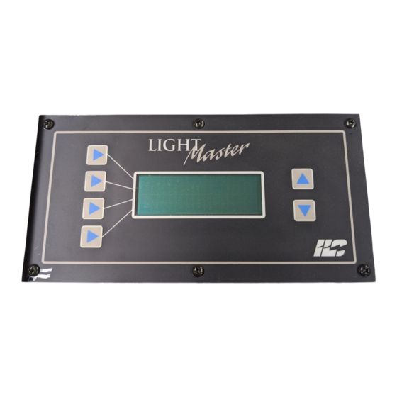
- Page 16 CPU I/O board. (See Figure 1.2.) Each relay output controls only one lighting relay. 4-line, 32-character Display Screen Scrolling Pads Selection Keys (Used to select Figure 1.4 – Light Master Keypad and Display displayed options) Light Master User Manual 1 - 8 Version 1C 9/20/00...
- Page 17 Controller Description 1.2 I/O Options The Light Master controller can be equipped with the following add-on devices: 1.2.1 Telephone Add-On Module – You can equip the controller with a DTMF (Dual Tone Multi Frequency) interface, which allows you to activate switch inputs via commands from a touchtone telephone.
- Page 18 Section 2 Installation LIGHT MASTER WED 10/30/99 07:50:54 AM EDIT (c) 99 ILC Light Master User Manual Version 1C 9/20/00...
- Page 19 2.6 Troubleshooting................2.6.1 Controller Will Not Power-Up ..........2.6.2 Lighting Relay(s) Will Not Function........2.6.3 Switch Input Will Not Function..........2.6.4 Timers Will Not Function Properly ........2.6.5 Entire I/O Board(s) Doesn’t Work ........Light Master User Manual Version 1C 9/20/00...
- Page 20 Section 2 – Installation Objectives Overview This section shows you how to install the This section covers the following topics: Light Master Programmable Contactor and how to perform required power-up • Pre-installation checks verification checks. • Mounting the controller • Wiring the controller •...
- Page 21 Perform the following procedures to wire the verify that the material is appropriate for line and control circuits of the Light Master. Do the project. Check to ensure that the NOT apply power to any circuits until instruct- voltages of the controller(s) transformers ed to do so.
- Page 22 Jumper W1- Relay response (on Grounding I/O board under programming Conductor module) Brown (277 VAC Hot) White(Neutral) Black (120 VAC Hot) Line Load Lighting Relay Figure 2.1 – Terminate Line to Control Transformer Primary Light Master User Manual 2 - 3 Version 1C 9/20/00...
- Page 23 Status LEDs Status LEDs LED Common (Grey) LED (Orange) to LED terminal of relay controlled Applies to pilot lighted switches only Figure 2.2 – Wire Class 2 Switch Circuits Light Master User Manual 2 - 4 Version 1C 9/20/00...
- Page 24 Installation 2.4 Pre-Power Checks 2.5 Power-Up and Check Out Complete the following checks BEFORE Complete the following procedures to applying power to the Light Master power-up and checkout the Light Master controller. controller. 2.4.1 Check Controller Power Input 2.5.1 Power-Up the Controller 1.
- Page 25 LED lights when it senses a switch closure. 6. If the switch input status LED lights and the relays function properly, there is prob- ably a problem with the field wiring. Light Master User Manual 2 - 6 Version 1C 9/20/00...
-
Page 27: Section 3 Programming
Section 3 Programming LIGHT MASTER WED 10/30/99 07:50:54 AM EDIT (c) 99 ILC Light Master User Manual Version 1C 9/20/00... -
Page 28: Section Overview
3.23 Capture Preset ................3-31 3.24 Set Open/Close Times..............3-33 3.24.1 Example: Set Open/Close Times........3-34 3.24.2 Example: Define the Timers ..........3-35 3.24.3 Example: Map Lighting Relays to Timers......3-36 3.25 Firmware Revision ................ 3-37 Light Master User Manual Version 1C 9/20/00... - Page 29 3-wire momentary switches are used exclusively at your facility, switch input definition will not be necessary. LIGHT MASTER WED 10/30/99 07:50:54 AM EDIT (c) 99 ILC Figure 3.1 - Light Master Home Screen Light Master User Manual 3 -1 Version 1C 9/20/00...
-
Page 30: Relay Status
WED 10/30/99 07:50:54 PM EDIT (C) 99 ILC EDIT EXIT RELAY STATUS RELAY OUTPUT SWITCH STATUS RELAY STATUS RELAY: 01 IS OFF SWEEP Relay Status EXIT Screen Flow Figure 3.2 Light Master User Manual 3 - 2 Version 1C 9/20/00... -
Page 31: Controlling Relays From The Keypad
ALL RELAYS OFF. ALL RELAYS OFF EXIT 6. Press EXIT to return to the top level Relay Status Step 5 screen. 7. Press EXIT to return to the Home screen. Light Master User Manual 3 - 3 Version 1C 9/20/00... -
Page 32: Relay Output
There are two additional choices available. impending OFF timers and the application/ You can program the relay output to turn ON re-application of power to the Light Master if switch input number 1 is ON (ON/IN:1) or controller. The controller blinks (momentarily... -
Page 33: Set Relay Parameters
POWERUP until the desired relay response to RELAY RELAY: 01 TIMERS NO BLINK a controller powerup appears. POWERUP NO ACTION EXIT Step 4 5. Press EXIT twice to return to the Home screen. Light Master User Manual 3 - 5 Version 1C 9/20/00... -
Page 34: Switch Status
07:50:54 PM EDIT (C) 99 ILC EDIT EXIT RELAY STATUS RELAY OUTPUT SWITCH STATUS SWITCH STATUS HOLD INPUT: 01 SCAN ON: CLOSED OFF: OPEN EXIT Switch Status Definition Screens Figure 3.4 Light Master User Manual 3 - 6 Version 1C 9/20/00... -
Page 35: View Current Switch Status
EXIT Step 1 2. If you press SCAN while viewing an input, the controller will automatically display the input that has changed state. 3. Press EXIT to leave the screen. Light Master User Manual 3 - 7 Version 1C 9/20/00... -
Page 36: Switch Input
WHAT IS IT? switch type function. Switch input is used to program the character- HOW DO I GET THERE? istics of each Light Master controller input. Each of the controller inputs can be connect- 1. From the Home screen, press EDIT;... -
Page 37: Programming A Switch Input
4. Press TYPE; then press until the desired switch type appears on the screen. Steps 3 & 4 5. Press EXIT; then press EXIT again to return to the Home screen. Light Master User Manual 3 - 9 Version 1C 9/20/00... - Page 38 Output Override 2-wire As long as the switch is closed, selected relay output(s) will ignore all maintained input, timer, or network commands. Table 3.1 – Light Master Switch Types Light Master User Manual 3 - 10 Version 1C 9/20/00...
- Page 39 EDIT; then twice RELAY STATUS RELAY OUTPUT SWITCH STATUS SWITCH/RELAY CONTROL SWITCH/RELAY CONTROL INPUT INPUT: 01 RELAY RELAY: 04 ACTION ON AND OFF EXIT MNT ON/OFF Input/Relay Definition Screens Figure 3.6 Light Master User Manual 3 - 11 Version 1C 9/20/00...
-
Page 40: Input/Relay Control
5. Press ACTION; then press until the desired relay Steps 3, 4, 5 response appears. 6. Press EXIT; then press twice and EXIT again to return to the Home screen. Light Master User Manual 3 - 12 Version 1C 9/20/00... -
Page 41: Timers
WHAT IS IT? Timers are time-based events that impact HOW DO I GET THERE? selected relay outputs. The Light Master con- troller supports up to 48 different timers. Each 1. From the Home screen, press EDIT; then... - Page 42 15 to 120 minutes before or after these times in 15-minute increments. See Figure 3-8 for ASTRO TIMER programming path. Light Master User Manual 3 - 14 Version 1C 9/20/00...
- Page 43 EXIT EXIT DAILY DAYS TIMER: 01 TIMER: 01 DAILY DAILY HOLIDAY SUNDAY EXIT EXIT ACTIVE: YES HOLIDAY TIMER: 01 MONTH (HOLIDAY) DATE 01/01 EXIT Timer Definition Screens (Astro) Figure 3.8 Light Master User Manual 3 - 15 Version 1C 9/20/00...
-
Page 44: Define A Timer
TIMER: 01 (DAILY) SUNDAY EXIT ACTIVE: YES 9. Press EXIT twice; then press 3 times, and EXIT once more to return to the Home screen. Step 8 Light Master User Manual 3 - 16 Version 1C 9/20/00... -
Page 45: Timer/Relay Control
(C) 99 ILC EDIT; then 4 times SWITCH INPUT INPUT/RELAY CONTROL TIMERS TIMER/RELAY CONTROL TIMER/RELAY CONTROL TIMER INPUT: 01 RELAY RELAY: 04 ACTION TURN OFF EXIT Timer/Relay Definition Screens Figure 3.9 Light Master User Manual 3 - 17 Version 1C 9/20/00... -
Page 46: Map The Timer To A Relay Output
5. Press ACTION; then press until the desired relay response appears. Steps 3, 4, 5 6. Press EXIT; then press 4 times and EXIT again to return to the Home screen. Light Master User Manual 3 - 18 Version 1C 9/20/00... -
Page 47: Blink Alerts
BLINK ALERTS to HID delay or alarm function, you must specify access the Blink Alert Settings screen. (See when the Light Master controller will execute Figure 3.10.) the alert. The choices are from 1 to 5 minutes before the OFF Timer; 5 minutes is the default. - Page 48 ALERT 05 MINUTES 2. Press OVERRIDE until the desired Timed ON OVERRIDE 1 HOUR EXIT override duration appears. Steps 1&2 3. Press EXIT to leave the Blink Alert Settings screen. Light Master User Manual 3 - 20 Version 1C 9/20/00...
-
Page 49: Set Time And Date
SET TIME AND DATE from the WHAT IS IT? menu of screen choices. (See Figure 3.11.) This is how you set the Light Master controller’s clock to the proper time and date. This oper- ation is necessary to implement the time- based control features of the controller. -
Page 50: Set The Controller Clock
WEDNESDAY day of the week is displayed. SAVE Step 12 13. Press SAVE. 14. Press EXIT; then press 6 times and then EXIT to return to the Home screen. Light Master User Manual 3 - 22 Version 1C 9/20/00... -
Page 51: Set Astro Clock
LATITUDE LATITUDE: 045 LATITUDE: 045 LONGITUDE LONGITUDE: 090 TIME ZONE: CENTRAL EXIT R=06:37 S=16:47 EXIT LONGITUDE: 090 TIME ZONE EXIT TIME ZONE: CENTRAL Astro Clock Definition Screens EXIT Figure 3.12 Light Master User Manual 3 - 23 Version 1C 9/20/00... - Page 52 (Note that the current sunrise and sunset times for the entered coordinates are TIME ZONE: CENTRAL EXIT also displayed on the screen.) Step 3 4. Then press EXIT to save the entries. Light Master User Manual 3 - 24 Version 1C 9/20/00...
-
Page 53: Daylight Savings
DAYLIGHT SAVINGS to access the Daylight Savings WHAT IS IT? screen. (See Figure 3.13.) The Light Master controller supports automatic adjustment of the system clock for Daylight Savings Time. The default is for automatic adjustment between Standard and Daylight Savings on the currently established dates. - Page 54 ENABLE DISABLE (Note that the screen displays whether Daylight EXIT CURRENT:STD Savings or Standard Time is current. 2. Press EXIT to save the data and leave the screen. Steps 1&2 Light Master User Manual 3 - 26 Version 1C 9/20/00...
-
Page 55: Serial Interface
LIGHT MASTER WED 10/14/99 07:50:54 PM EDIT (C) 99 ILC EDIT; then 9 times SERIAL INTERFACE ILC PROTOCOL REV. 5.08 01/28/99 EDIT ADDRESS: 001 Serial Interface Definition Screens Figure 3.14 Light Master User Manual 3 - 27 Version 1C 9/20/00... -
Page 56: Telephone Interface
EXIT Telephone Interface Screen ELITE SERIAL 1-2 W/TELEPHONE REV. 1.00 01/28/99 EXIT EDIT; then 10 times ILC PROTOCOL REV. 5.08 01/28/99 EXIT ADDRESS: 001 Telephone Interface Definition Screens Figure 3.15 Light Master User Manual 3 - 28 Version 1C 9/20/00... -
Page 57: Edit Presets
EDIT; then 11 times DAYLIGHT SAVINGS SERIAL INTERFACE TELEPHONE PORT EDIT PRESETS EDIT PRESETS PRESET PRESET: 001 RELAY RELAY: 01 ACTION TURN ON EXIT Edit Presets Definition Screens Figure 3.16 Light Master User Manual 3 - 29 Version 1C 9/20/00... - Page 58 3. Press ACTION; then until the desired state appears. 4. After you have edited all the relays to be changed, press EXIT to save the changes and leave the screen. Light Master User Manual 3 - 30 Version 1C 9/20/00...
-
Page 59: Capture Preset
Capture Preset screen. (See Figure 3.17.) WHAT IS IT? The Light Master supports the ability to save the current states of the relay outputs. You can use this stored information to set the relay outputs to the same pre-determined states anytime in the future. - Page 60 Capture Relay screen again, select the appropriate PRESET, then press TEST. The controller will set the relay outputs to that preset’s states. Light Master User Manual 3 - 32 Version 1C 9/20/00...
-
Page 61: Set Open/Close Times
WED 10/30/99 07:50:54 PM EDIT (C) 99 ILC EDIT; then 14 times OPEN/CLOSE TIMES SET OPEN 12:00 AM SET CLOSE 12:00 AM EXIT Set Open/Close Time Definition Screens Figure 3.18 Light Master User Manual 3 - 33 Version 1C 9/20/00... -
Page 62: Example: Set Open/Close Times
SET CLOSE and set the Close Time at 9:00 PM. OPEN/CLOSE TIMES SET OPEN 09:00 AM SET CLOSE 09:00 PM EXIT 8. Press EXIT to return to the menu screens. After Step 7 Light Master User Manual 3 - 34 Version 1C 9/20/00... -
Page 63: Example: Define The Timers
OPEN/CLOSE. 9. Press CLOSE; then until CLS+15 MN appears. 10. Press EXIT to return to the top level Timer Definition Screen. Then EXIT again to return to the menu screens. Light Master User Manual 3 - 35 Version 1C 9/20/00... - Page 64 Top Level Screen (After Step 6) 8. Repeat steps 4 to 6 except that you select TURN OFF for the relay action. 9. Let the controller time out to save the entries. Light Master User Manual 3 - 36 Version 1C 9/20/00...
-
Page 65: Firmware Revision
QUANTA ELITE WED 10/14/98 07:50:54 PM EDIT (C) 98 ILC EDIT; then 15 times ILC ELITE LIGHTING CONTROLLER REV 5.05 12/07/98 EXIT 08/I/0 POINTS Firmware Revision Definition Screens Figure 3.19 Light Master User Manual 3 - 37 Version 1C 9/20/00... - Page 66 Section 4 Applications LIGHT MASTER WED 10/30/99 07:50:54 AM EDIT (c) 99 ILC Light Master User Manual Version 1C 9/20/00...
-
Page 67: Section 4 Applications
4.5.2 Map the BAS System Contact to the Relays..... 4-11 4.6 Control Relays by Time of Day Schedules ........4-12 4.6.1 Set the Light Master Clock to Current Date and Time ..4-13 4.6.2 Define the Timers ..............4-14 4.6.3 Map the Timer to the Relays .......... - Page 68 Another term used often is Home screen. The • Home screen is the top level screen of the How to interface the Light Master relay controller. It features the controller name, the outputs with several load devices. date, and the time. (See Figure 4-1.) The con- •...
-
Page 69: Wire And Program A 3-Wire Spdt Momentary Switch To Control Relays
1 and program the controller so that it Wiring and programming a momentary switch controls relays 5 and 6. to control one or more of the Light Master’s relays consists of three main operations. 1. Wire the switch to one of the controller switch inputs. -
Page 70: Map The Switch To The Relays
6. Repeat steps 4 and 5 for RELAY: 06. Step 2 7. Let the controller time out and save your entries. INPUT INPUT: 01 RELAY RELAY: 05 ACTION ON AND OFF EXIT MOM ON/OFF Steps 3, 4 and 5 Light Master User Manual Version 1C 9/20/00... -
Page 71: Wire And Program A 2-Wire Maintained Switch To Control Relays
Wiring and programming a maintained switch relays 7 and 8. to control one or more of the Light Master’s relays consists of three main operations. Wire the switch to one of the controller switch inputs. -
Page 72: Map The Switch To The Relays
Repeat steps 4 and 5 for RELAY: 08. Let the controller time out and save your entries INPUT INPUT: 02 RELAY RELAY: 07 ACTION ON AND OFF EXIT MNT ON/OFF Steps 3, 4 and 5 Light Master User Manual Version 1C 9/20/00... -
Page 73: Wire And Program A Photocell Controller Contact To Control Relays
Wiring and programming a photocell con- trols relays 2 and 3. troller contact to control one or more of the Light Master’s relays consists of three main operations. Wire the photocell contact to one of the controller switch inputs. (See Figure 4-4.) Define the Switch Type. -
Page 74: Map The Photocell Contact To The Relays
Repeat steps 4 and 5 for RELAY: 03. Let the controller time out and save your entries. INPUT INPUT: 01 RELAY RELAY: 02 ACTION ON AND OFF EXIT MNT ON/OFF Steps 3, 4 and 5 Light Master User Manual Version 1C 9/20/00... -
Page 75: Wire And Program An Occupancy Sensor Contact To Control Relays
Wiring and programming an occupancy sen- that it controls relays 2 and 3. sor contact to control one or more of the Light Master’s relays consists of three main operations. Wire the power pack contact to one of the controller switch inputs. (See Figure 4-5.) Define the Switch Type. -
Page 76: Map The Occupancy Sensor Contact To The Relays
Repeat steps 4 and 5 for RELAY: 03. INPUT INPUT: 05 RELAY RELAY: 02 Let the controller time out and save your entries. ACTION ON AND OFF EXIT MNT ON/OFF Steps 3, 4 and 5 Light Master User Manual Version 1C 9/20/00... -
Page 77: Wire And Program A Bas System Contact To Control Relays
3 and 4. The BAS contact is maintained. automation system) contact to control one or Note: the BAS output must be DRY contact. more of the Light Master’s relays consists of Triac or other solid state outputs require indi- three main operations. -
Page 78: Map The Bas System Contact To The Relays
Repeat steps 4 and 5 for RELAY: 04. Let the controller time out and save your entries. INPUT INPUT: 06 RELAY RELAY: 03 ACTION ON AND OFF EXIT MNT ON/OFF Steps 3, 4 and 5 Light Master User Manual 4-11 Version 1C 9/20/00... -
Page 79: Control Relays By Time Of Day Schedules
Assume the current date/time is Tuesday three main operations. 10:27 AM, 2/15/00. Set the Light Master clock to the current NOTE: time and date. The controller is defaulted to automatically Define the timers. -
Page 80: Set The Light Master Clock To Current Date And Time
Applications 4.6.1 Set the Light Master Clock To the Current Date and Time HOUR 10:27 AM 1. From the Home screen, press EDIT; then 6 times. MINUTE EXIT 2. Press SET TIME AND DATE. Steps 4-6 3. Press TIME. 4. Press HOUR;... -
Page 81: Define The Timers
NO. (YES for Monday-Friday, NO for Saturday and Sunday.) 10. Repeat steps 3 to 9 for TIMER: 06. 11. Let the controller time out and save your entries. TIMER: 05 (DAILY) TUESDAY EXIT ACTIVE: YES Step 8 Light Master User Manual 4-14 Version 1C 9/20/00... -
Page 82: Map The Timer To The Relays
TURN OFF ACTION TURN ON EXIT appears. Steps 3, 4 and 5 10. Repeat steps 8 and 9 for RELAY: 05 11. Let the controller time out and save your entries. Light Master User Manual 4-15 Version 1C 9/20/00... -
Page 83: Wiring To Field Loads
It is also possible for the relays to control the coils of electrically and mechanically held contactors. (See Figures 4.8 and 4.9.) ORANGE ORANGE STATUS BLACK (OFF) RED (ON) Light Master Controller Board BLUE (COM) Relay output Line termination detail O F F Load 2R9C Relay... - Page 84 Applications ORANGE ORANGE STATUS BLACK (OFF) RED (ON) Light Master Controller Board BLUE (COM) Relay output Line termination detail O F F Load 2R9C Relay Neutral O F F P I L OT V 1 0 C OM + Motor:...
- Page 85 MOV collapsing magnetic field may produce a across the contactor coil. voltage spike that may impact the lighting 120V De-spiking Kit: Light Master Controller Board Part # 9300367 277V De-spiking Kit: Line (120 or 277 VAC) Part # 9300368 “De-spiking Cap.”...
- Page 86 Applications Light Master Controller Board Line (120 or 277 VAC) Line (Contactor control circuit) Load 2R9C Relay To contactor ON PILOT Line COM + To contactor OFF Load COIL Neutral Control Relay Figure 4.9 - Mechanically Held Contactor Interface Light Master User Manual...
- Page 87 Section 5 Appendix LIGHT MASTER WED 10/30/99 07:50:54 AM EDIT (c) 99 ILC Light Master User Manual Version 1C 9/20/00...
-
Page 88: Section 5 Appendix
M.3 Transmission Modes ..............M.4 Transmission Mode Characteristics........M.5 Hardware Setup..............M.6 Required Parameter Entries........... M.7 Framing ..................M.8 Additional Information............N. N2 Communications ............... N.1 Overview .................. N.2 Hardware Setup ..............N.3 Point Map................. Light Master User Manual Version 1C 9/20/00... - Page 89 If they do, you will be given advance notice so as to give you an opportunity to maintain uninterrupted service. If you experience trouble with this telephone equipment, please contact: Intelligent Lighting Controls, Inc./Reliant Relay Co., Technical Support Department at 1-800-922-8004 for repair and warranty information. If your equipment is causing harm to the telephone network, the telephone company may request that you disconnect the equipment until the problem is resolved.
- Page 90 You can link a personal computer (PC) equipped with a modem and QUANTA Pro • Get the current status of the controller’s networking software to the Light Master relay outputs controller and perform all the control and • Turn ON or OFF single relays or groups of...
- Page 91 Appendix A: Telephone Add-On Module Light Master Controller 7701 3396 9701 3396 Touchtone Telephone Unused Expansion Slot Telephone System RJ11 Phone Jack RJ11 Phone Jack Telephone Add-on Module Figure A.1 – DTMF Phone Control Light Master User Manual A - 3 Version 1C 9/20/00...
- Page 92 QUANTA Pro software 96 REV 770 133 96 REV 970 133 Unused Expansion Slot Telephone System RJ11 Phone Jack RJ11 Phone Jack Telephone Add-On Module Figure A.2 – Remote Modem Control Light Master User Manual Version 1C 9/20/00...
- Page 93 B.2 PC Add-On Setup The PC Add-On Module allows you to 1. If you are field-installing the module, program the Light Master controller using a power-down the controller and plug personal computer (PC) equipped with the module into an unused expansion QUANTA Pro software.
-
Page 94: Pc Add-On Module
Light Master Controller Personal Computer equipped with QUANTA Pro software Unused Expansion Slot RS-232 Port PC Add-On Module Factory-supplied RS232 cable to computer COM port Figure B.1 – Programming the Controller from a PC Light Master User Manual Version 1C 9/20/00... -
Page 95: Overview
CPU board. (See Figure D-1.) You can program the Light Master with desired ON and OFF DMX signal levels and then select how the Light Master relay out- puts will respond. You set common ON and OFF DMX signal levels for all DMX 512 channels (1 to 512 channels). - Page 96 1-ON, 2-OFF = 128 channels enabled 1-OFF, 2-ON = 256 channels enabled 1-ON, 2-ON = 512 channels enabled DMX 512 Interface Card Mounted on Light Master Controller CPU Board Light Master Controller 100 ohm Terminating Resistor (Used only if Light Master Controller...
-
Page 97: Programming Example
EXIT to return to the DMX menu. DMX – Relay Control 13. Press EXIT to return to the main menu. Let the controller time out to save your entries and return to the Home screen. Light Master User Manual Version 1C 9/20/00... -
Page 98: Modbus Communications
Both provide the same com- sensing, and control devices. By setting the munication capabilities. The mode slected protocol jumpers on the Light Master depends on the equipment used as the Controller QSLI plug in LAN Module, and set- MODBUS master. - Page 99 Appendix M: MODBUS Communications Light Master MODBUS Comunications Example – See Termination Detail Below Light Master MODBUS – 32 and Serial/LAN Module MODBUS COMM. Terminal on Serial/LAN Card- Detail Data Line – 2 #18 AWG Shield Pair POS, Drain, NEG...
-
Page 100: Transmission Mode Characteristics
M.5 Hardware Setup The Light Master must be equipped with a QSLI LAN module that is jumpered for MOD- BUS communications and addressed with a unique node address. (See Figure M-1.) The network cable is a two wire shielded twisted pair. - Page 101 Press PARITY until the desired parity appears. Press EXIT or let the controller time out to save the entries. PROTOCOL ASCII BAUD RATE 19200 PARITY EXIT ADDRESS:002 MODBUS Top Configuration Screen Figure M-2 Light Master User Manual Version 1C 9/20/00...
- Page 102 0= Input Open 1 = Input Closed 0= Input Open 1 = Input Closed 0= Input Open 1 = Input Closed 0= Input Open Table M.1 – Light Master Data Field Input Point Designators Light Master User Manual Version 1C 9/20/00...
- Page 103 1=Output Closed 0=Output Open 1=Output Closed 0=Output Open 1=Output Closed 0=Output Open 1=Output Closed 0=Output Open 1=Output Closed 0=Output Open 1=Output Closed 0=Output Open Table M.1.1 – Light Master Data Field Output Point Designators Light Master User Manual Version 1C 9/20/00...
-
Page 104: Overview
N.1 Overview N.3 Point Map The Light Master Controller(s) can be inte- Fill out the point map for the Light Master grated into a Building Automation System Controller. Note that only BI and BO point (BAS) that uses the N2 communications pro- types are used. - Page 105 Appendix N: N2 Commmunications Light Master N2 Network Example – See Termination Detail Below Light Master N2 – 32 and Serial/LAN Module N2 COMM. Terminal on Serial/LAN Card- Detail Data Line – 2 #18 AWG Shield Pair N2+, Ref., N2-...
- Page 106 SWITCH INPUT #10 ON 0-OPEN 1-CLOSED SWITCH INPUT #11 OFF 0-OPEN 1-CLOSED SWITCH INPUT #11 ON 0-OPEN 1-CLOSED SWITCH INPUT #12 OFF 0-OPEN 1-CLOSED SWITCH INPUT #12 ON 0-OPEN 1-CLOSED Table N.1 – Light Master N2 Point Map Light Master User Manual Version 1C 9/20/00...
- Page 107 SWITCH INPUT #23 OFF 0-OPEN 1-CLOSED SWITCH INPUT #23 ON 0-OPEN 1-CLOSED SWITCH INPUT #24 OFF 0-OPEN 1-CLOSED SWITCH INPUT #24 ON 0-OPEN 1-CLOSED SWITCH INPUT #25 OFF 0-OPEN 1-CLOSED Table N.1 – Light Master N2 Point Map Light Master User Manual Version 1C 9/20/00...
- Page 108 SWITCH INPUT #35 OFF 0-OPEN 1-CLOSED SWITCH INPUT #35 ON 0-OPEN 1-CLOSED SWITCH INPUT #36 OFF 0-OPEN 1-CLOSED SWITCH INPUT #36 ON 0-OPEN 1-CLOSED SWITCH INPUT #37 OFF 0-OPEN 1-CLOSED Table N.1 – Light Master N2 Point Map Light Master User Manual Version 1C 9/20/00...
- Page 109 SWITCH INPUT #46 ON 0-OPEN 1-CLOSED SWITCH INPUT #47 OFF 0-OPEN 1-CLOSED SWITCH INPUT #47 ON 0-OPEN 1-CLOSED SWITCH INPUT #48 OFF 0-OPEN 1-CLOSED SWITCH INPUT #48 ON 0-OPEN 1-CLOSED Table N.1 – Light Master N2 Point Map Light Master User Manual Version 1C 9/20/00...
- Page 110 RELAY OUTPUT #20 0-OFF 1-ON RELAY OUTPUT #21 0-OFF 1-ON RELAY OUTPUT #22 0-OFF 1-ON RELAY OUTPUT #23 0-OFF 1-ON RELAY OUTPUT #24 0-OFF 1-ON Table N.1 – Light Master N2 Point Map Light Master User Manual Version 1C 9/20/00...
- Page 111 RELAY OUTPUT #44 0-OFF 1-ON RELAY OUTPUT #45 0-OFF 1-ON RELAY OUTPUT #46 0-OFF 1-ON RELAY OUTPUT #47 0-OFF 1-ON RELAY OUTPUT #48 0-OFF 1-ON Table N.1 – Light Master N2 Point Map Light Master User Manual Version 1C 9/20/00...
- Page 112 Section 4– Applications Light Master User Manual...
Need help?
Do you have a question about the Light Master and is the answer not in the manual?
Questions and answers