
Summary of Contents for Nortek Linear eMerge e3 Series
- Page 1 e3 eMerge Access Control System Document Number: 620-100531, Rev. B Installation Instructions...
- Page 2 Notices All rights strictly reserved. No part of this document may be reproduced, copied, adapted, or transmitted in any form or by any means without written permission from Nortek Security & Control LLC. Standards Approvals This equipment has been tested and found to comply with the limits for a Class A digital device, pursuant to part 15 of the FCC Rules.
-
Page 3: Table Of Contents
Contents 1.0 Introduction ................1.1 Access Control Overview. -
Page 4: Introduction
1.0 Introduction Th is manual contains information regarding the basic installation, wiring and confi guration of the e3 eMerge browser-based access control systems. Systems are available in a space-effi cient and durable plastic housing or in a heavy-duty steel cabinet featuring a self-contained battery back-up with a supervised power supply. -
Page 5: Installation Overview Checklist
1.3 Installation Overview Checklist Note: The checklist Th e following list presents the steps required for successfully installing a system. provides a logical ❒ Mount the enclosure sequence for installing a system. ❒ Connect the readers ❒ Wire the inputs and outputs ❒... -
Page 6: Control Panel Layout
2.0 Control Panel Layout 2.1 Control Panel Components Th e following illustration shows the e3 control panel wiring and components. IN READER OUT READER OUT READER IN READER EARTH GROUND & DOOR 4 DOOR 3 READER SHIELD LEAD DOOR 3 LOCK LAN LED DL19 DL18... -
Page 7: Installing The Control Panel
3.0 Installing the Control Panel 3.1 Mounting the Compact Enclosure Th e housing is designed to accommodate the necessary wiring connections for most installations. Th e compact enclosure is optimized to run wires under the back panel and thru the knockouts Note: This device complies with Part shown in Figure 3.1 and Figure 3.2. - Page 8 Mounting Extensions If running surface wires, 6 extension legs may be snapped onto the back of the enclosure to provide additional space behind the enclosure for the wires. Figure 3.2. Mounting Feet / Extensions for Compact Enclosure www.linearcorp.com e3 eMerge Installation Instructions...
-
Page 9: Mounting The Metal Enclosure
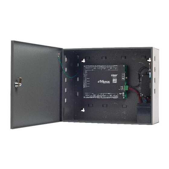
3.2 Mounting the Metal Enclosure Th e metal enclosure is designed to accommodate one or two 12VDC 7Ah backup batteries and Note: Choose a centrally the necessary wiring connections for most installations. Conduit knock-outs are provided on all located, secure, clean sides of the enclosure. -
Page 10: System Power
4.0 System Power Th e system panel requires a 12VDC, 2A supply (not included). For UL installations, a Linear Plug in Power supply (PIP) is required (see below). Th e system may also be powered by a high Power over Ethernet (PoE) injector using an optional Linear PoE module. ♦... - Page 11 Power Fault Connection Th e controller is equipped with a power fault input that can be utilized as follows: Note: The system settings must match the 1. Determine whether your power fault input device uses a normally closed or normally open requirement (normally confi guration.
-
Page 12: Power Connection For Systems Using Metal Enclosure
4.2 Power Connection for Systems using the Metal Enclosure Systems using metal enclosures include a factory installed power supervision module as shown in Figure 4.3. Caution: A 12VDC power Power Supply Connection supply MUST be used. 1. Connect 12VDC from the included power supply to the RED (+) and BLACK (-) leads Incorrect voltage will on the panel. -
Page 13: Poe Connection (Optional)
To determine standby battery time: 1. Determine the total standby load of the system by adding the maximum and standby current Note: Each controller draw of the devices connected to the panel. For example, if the system consists of the control consumes 200 mA of panel (200 mA) and one 75 mA reader the total standby load is 275 mA (200 mA+ 75 mA). -
Page 14: Inputs And Outputs
5.0 Inputs and Outputs 5.1 System Inputs Systems have the capability of monitoring door status (door contact) inputs, request to exit (REX) inputs, and auxiliary general purpose inputs. All inputs are assigned default features that can be confi gured as needed. Th e following table shows the default states for each of the inputs: Table 5.1: Default Input States Input... -
Page 15: Wiring The Inputs
5.2 Wiring the Inputs All inputs may be confi gured for normally open (factory default) or normally closed contacts with supervision or non-supervision. Use standard 1k ohm resistors for supervision. Refer to Figure 5.1 for the acceptable wiring confi gurations. SUPERVISED UNSUPERVISED Minimum Cable... -
Page 16: System Outputs
5.3 System Outputs All systems have door lock relays and auxiliary output relays that may be activated in response to reader activity, time schedules or input conditions. All relays are Form-C SPDT and provide non-powered dry contacts rated for 2A. Th e number of available door lock relays and auxiliary output relays will depend on the number of licensed doors. -
Page 17: Door Lock Outputs
5.4 Door Lock Outputs Th e door lock outputs can be confi gured to operate in fail-secure or fail-safe modes. Wiring the Door Locks Connect locking devices to the door relay as shown in Figures 5.3 through 5.5. Refer to the door strike specifi cations to determine the appropriate voltage and confi guration. -
Page 18: Readers
6.0 Readers 6.1 Wiring the Readers Th e control panel can accept up to 8 readers or keypads. Each reader port on the panel supports a 12VDC reader with Wiegand output format. Readers can be installed as primary (entry) readers for each door as well as optional secondary (exit) readers. -
Page 19: Network Connection
7.0 Network Connection Th e controllers must be located in a trusted network environment where a protected network security system (fi rewall, etc.) is installed and maintained. Obtain the following information from Caution: The system is your network administrator before confi guring the controller: exposed to potential risks if installed on a network ♦... -
Page 20: Connecting To The Network
5. Browse to the Network Confi guration (IP address) page as shown in Figure 7.3. Enter the static IP address, Subnet Mask, Gateway and DNS server so that it matches the requirements of the local network. (Refer to the User Manual for complete programming information.) Figure 7.3. - Page 21 LAN LEDS Note: LAN connection is only required for monitoring, reporting DL19 and confi guration. Once DL18 confi gured, systems will operate without a LAN ETHERNET connection. Figure 7.5. LAN LEDs www.linearcorp.com e3 eMerge Installation Instructions...
-
Page 22: Adding A Client
7.3 Adding a Client Some e3 eMerge systems provide the ability to add additional controllers to expand the amount of doors or elevator control, inputs and outputs. Th ese additional controllers are referred to as clients. A client can be mounted on top of the main controller (server) for systems using metal enclosures or in a separate enclosure. -
Page 23: Configuring The Client And Server On The Network
7.4 Configuring the Client and Server on the Network IP Installer is a utility located on a thumb drive shipped with all systems. Th e purpose of this utility is to locate the server and client on the network. It also provides a simple method of changing the IP address of the controller(s). - Page 24 Assign the Server to Client After the controllers are located on the network, the client must be linked to the server as follows: 1. Using a web browser on a local computer, enter the IP address of the client as confi gured in IP Installer.
- Page 25 Enter e3 Server IP address Enter password and click Save 5. Enter the IP address of the server as entered in IP Installer. 6. Enter the password (default = admin) and click Save. Link the Client to Server 1. Using a web browser on a local computer, enter the IP address of the server as listed in IP Installer.
-
Page 26: Programming The System
5. Th e client will appear in the list. Click the Use/Not Use button to link the client to the server. Th e button will display Use when the client is successfully linked to the server. 6. Click the Door icon and verify that the client doors are listed. Th e client and server are now linked together. -
Page 27: Troubleshooting
For further troubleshooting assistance, please visit the following online resources: ♦ http://www.nortekcontrol.com/faq/ ♦ http://www.learnlinear.com ♦ http://www.e3links.com Nortek Security & Control Technical Support: ♦ Tel: (800) 421-1587; ♦ Hours: 5:00 AM to 4:30 PM Pacifi c Time, M-F www.linearcorp.com e3 eMerge Installation Instructions... -
Page 28: Test, Maintenance And Service
Linear 30W PoE injector ..............POE-PLUS Linear 12VDC/24W PIP ..............0-291312RU Linear 12VDC/60W PIP (recommended power supply) ......0-299177RU Replacement Power Supervision/Battery Charger Module ....620-100002 For a replacement Controller, please contact Nortek Security & Control Sales for support at 1-800-421-1587 www.linearcorp.com e3 eMerge Installation Instructions... - Page 29 D0 IN D1 IN D0 OUT D1 OUT INPUT DOOR INPUT CONTACT AUX INPUT 4 AUX IN AUX INPUT 3 AUX IN D0 IN D1 IN D0 OUT D1 OUT INPUT DOOR INPUT CONTACT www.linearcorp.com e3 eMerge Installation Instructions...
-
Page 30: Notes
10. Notes __________________________________________________________________________________ __________________________________________________________________________________ __________________________________________________________________________________ __________________________________________________________________________________ __________________________________________________________________________________ __________________________________________________________________________________ __________________________________________________________________________________ __________________________________________________________________________________ __________________________________________________________________________________ __________________________________________________________________________________ __________________________________________________________________________________ __________________________________________________________________________________ __________________________________________________________________________________ __________________________________________________________________________________ __________________________________________________________________________________ __________________________________________________________________________________ __________________________________________________________________________________ __________________________________________________________________________________ __________________________________________________________________________________ __________________________________________________________________________________ __________________________________________________________________________________ __________________________________________________________________________________ __________________________________________________________________________________ __________________________________________________________________________________ __________________________________________________________________________________ __________________________________________________________________________________ __________________________________________________________________________________ www.linearcorp.com e3 eMerge Installation Instructions... - Page 31 Notes __________________________________________________________________________________ __________________________________________________________________________________ __________________________________________________________________________________ __________________________________________________________________________________ __________________________________________________________________________________ __________________________________________________________________________________ __________________________________________________________________________________ __________________________________________________________________________________ __________________________________________________________________________________ __________________________________________________________________________________ __________________________________________________________________________________ __________________________________________________________________________________ __________________________________________________________________________________ __________________________________________________________________________________ __________________________________________________________________________________ __________________________________________________________________________________ __________________________________________________________________________________ __________________________________________________________________________________ __________________________________________________________________________________ __________________________________________________________________________________ __________________________________________________________________________________ __________________________________________________________________________________ __________________________________________________________________________________ __________________________________________________________________________________ __________________________________________________________________________________ __________________________________________________________________________________ __________________________________________________________________________________ www.linearcorp.com e3 eMerge Installation Instructions...
- Page 32 Copyright © 2015 Nortek Security & Control LLC 620-100531 B...
Need help?
Do you have a question about the Linear eMerge e3 Series and is the answer not in the manual?
Questions and answers