Table of Contents
Advertisement
Quick Links
9800 SERIES
FREQUENCY
CONVERTERS
STANDARD FREQUENCY
U-9848-1-1K
U-9848-5-1K
U-9853-2-1K
U-9854-1K
U-9856-6-1K
U-9857-2-1K
STANDARD FREQUENCY
D-9800-3-1K
D-9800-6-1K
D-9800-7-1K
D-9800-8-1K
D-9801-1-1K
*
OPTIONS 1, 4, 5, 8, 10B, 10C, 10E, 10F, 14, 15, 16C, 17C, 18-4, 18-8, 20, 31A THRU 31D,
TNCIF, NRF, TNCRF LISTED ON THE FOLLOWING PAGE.
MODEL NUMBER SUPPLIED
MODEL NUMBER SUPPLIED
UPCONVERTER
U-9848-4-1K
U-9848-6-1K
U-9853-6-1K
U-9855-2-1K
U-9856-7-1K
DOWNCONVERTER
D-9802-2-1K
D-9805-1K
D-9808-6-1K
®
REVERSE FREQUENCY
U-9801R-1-1K
U-9802R-2-1K
U-9805R-1K
U-9808R-6-1K
REVERSE FREQUENCY
D-9853R-2-1K
D-9853R-6-1K
D-9854R-1K
D-9855R-2-1K
D-9856R-6-1K
D-9856R-7-1K
D-9857R-2-1K
H a u p p a u g e , N e w Yo r k 11 7 8 8 - 2 0 3 4
1 0 0 D a v i d s D r i v e
Te l : 6 3 1 4 3 6 7 4 0 0
F a x : 6 3 1 4 3 6 7 4 3 1
w w w. m i t e q . c o m
Advertisement
Table of Contents

Related Manuals for Miteq 9800 Series

Summary of Contents for Miteq 9800 Series
- Page 1 ® 9800 SERIES FREQUENCY CONVERTERS MODEL NUMBER SUPPLIED MODEL NUMBER SUPPLIED UPCONVERTER STANDARD FREQUENCY REVERSE FREQUENCY U-9848-1-1K U-9848-4-1K U-9801R-1-1K U-9848-5-1K U-9848-6-1K U-9802R-2-1K U-9853-2-1K U-9853-6-1K U-9805R-1K U-9854-1K U-9855-2-1K U-9808R-6-1K U-9856-6-1K U-9856-7-1K U-9857-2-1K DOWNCONVERTER STANDARD FREQUENCY REVERSE FREQUENCY D-9800-3-1K D-9802-2-1K D-9853R-2-1K D-9800-6-1K...
- Page 2 9800 Series Frequency Converters ® 9800series, Rev.M, 2/5/2013 OPTIONS SUPPLIED OPTIONS SUPPLIED Option 1: 45 dB level control Option 4: 140 MHz IF Frequency Option 5: Group delay equalization 1.0 ns p-p maximum/70 ±18 MHz IF output 2.0 ns p-p maximum/140 ±36 MHz IF output Option 8: LO level detect Option 10B: Higher Frequency Stability Reference (see Section 1 for specifi...
- Page 3 9800 Series Frequency Converters ® 9800series, Rev.M, 2/5/2013 DOCUMENTATION REVISIONS The purpose of this section is to chronicle any and all changes made in this manual, in regards to both technical information concerning this piece of equipment, and the actual format/function of this document.
- Page 4 9800 Series Frequency Converters ® 9800series, Rev.M, 2/5/2013 3/9/09: REV.D TO REV.E (CONTINUED) PG.14 - ADDED AT2: Attenuation 2 PG.15 - ADDED Log Cleared, Power Supply fault/recovery, Attenuation 2 change AND AMP Current fault/recovery TO REPORTABLE EVENTS LIST PG.16 - REMOVED RTS/CTS PARAMETER AND REWROTE ALL OTHERS EXCEPT CONTROL IN REMOTE INTERFACE OPTION MENU PG.16 - REMOVED FIGURE 3-8a...
- Page 5 PG.9 - ADDED TO TABLE 2-1. EXTERNAL CONNECTIONS: Options 31A, 31B, 31C, 31D. PGS. 56 TO 69 - RENUMBERED PAGES FROM 56 THRU 69 TO 58 THRU 71. PG.56 - ADDED FIGURE 4-2. BLOCK DIAGRAM, 9800 SERIES NARROW BAND CONVERTERS FOR TT&C APPLICATION.
-
Page 6: Table Of Contents
9800 Series Frequency Converters ® 9800series, Rev.M, 2/5/2013 TABLE OF CONTENTS SECTION 1: INTRODUCTION ....................1 GENERAL DESCRIPTION .............................. 1 PHYSICAL ..................................1 MODEL NUMBERS ................................. 2 Converter Model Numbers ............................2 EQUIPMENT CHARACTERISTICS ..........................4 PHYSICAL ..................................4 Connector Wiring Information ..........................4 FUNCTIONAL ................................. - Page 7 9800 Series Frequency Converters ® 9800series, Rev.M, 2/5/2013 TABLE OF CONTENTS SECTION 3: OPERATION (CONTINUED) UNIT MUTE COMMAND WITHOUT LOG = MTN (N/A IN ALL MODELS)..............35 UNIT NAME = NAM...............................35 REFERENCE FREQUENCY ADJUSTMENT = REF (N/A IN ALL MODELS) ...............36 FIRMWARE TITLE AND REVISION = REV OR VER ....................36...
- Page 8 Figure 1-1. Front Panel, 9800 Series Converter........................1 Figure 1-2. Rear Panel, 9800 Series Converter ........................1 Figure 1-3. Rear Panel, 9800 Series Converter (S/N 1376398 and later) ................1 Figure 1-4. Rear Panel, 9800 Series with Option 31 ......................1 Figure 3-1.
-
Page 9: Section 1: Introduction
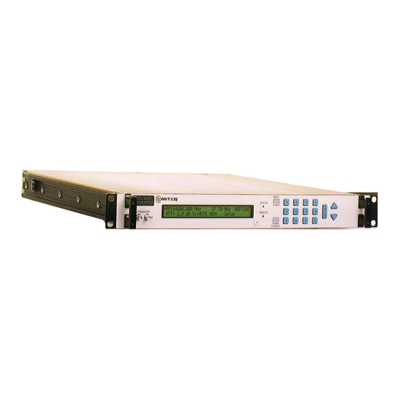
Power factor corrected power supply PHYSICAL Figure 1-1. Front Panel, 9800 Series Converter Figure 1-2. Rear Panel, 9800 Series Converter Figure 1-3. Rear Panel, 9800 Series Converter (Option NRF) External Reference External Reference (a “U” link is provided) Figure 1-4. Rear Panel, 9800 Series with Option 31... -
Page 10: Model Numbers
9800 Series Frequency Converters ® 9800series, Rev.M, 2/5/2013 MODEL NUMBERS Converter Model Numbers Standard Frequency Downconverters Standard Frequency Downconverters Model Number RF Input RF LO Second IF IF LO IF Output (GHz) (GHz) (MHz) (MHz) (MHz) D-9800-3-1K 0.95-1.75 4.68-5.55 3800 3870 3730 (Opt.4) - Page 11 9800 Series Frequency Converters ® 9800series, Rev.M, 2/5/2013 Standard Frequency Upconverters Standard Frequency Upconverters Model Number IF Input IF LO Second IF RF LO RF Output (MHz) (MHz) (MHz) (GHz) (GHz) U-9848-1-1K 3870 3800 4.68-5.55 0.95-1.75 140 (Opt.4) 3730 (Opt.4)
-
Page 12: Equipment Characteristics
9800 Series Frequency Converters ® 9800series, Rev.M, 2/5/2013 EQUIPMENT CHARACTERISTICS PHYSICAL Weight ............ 15 pounds nominal Chassis dimensions........ 19” x 1.75” panel height x 20” maximum Connectors RF ............SMA female (2.92 mm above 26 GHz) RF Monitor ........... SMA female (n/a above 17.7 GHz) IF ............ -
Page 13: Functional
9800 Series Frequency Converters ® 9800series, Rev.M, 2/5/2013 FUNCTIONAL Converter Performance Specifi cations Converter Performance Specifi cations Upconverter Downconverter Type Dual conversion Frequency step size 1 kHz Frequency sense No inversion Input characteristics Frequency 70 ±20 MHz Refer to model number table 140 ±40 MHz (Option 4) - Page 14 9800 Series Frequency Converters ® 9800series, Rev.M, 2/5/2013 Converter Performance Specifi cations (Continued) Converter Performance Specifi cations (Continued) Upconverter Downconverter Spurious outputs Signal related 65 dBc up to 0 dBm output, 60 dBc above 22 GHz Signal independent -70 dBm maximum...
- Page 15 9800 Series Frequency Converters ® 9800series, Rev.M, 2/5/2013 Phase Noise guaranteed provided external reference has the following phase noise - Phase Noise Specifi cations Phase Noise Specifi cations Standard Option 31 - Ultra-Low Phase Noise Model Number Offset (Hz) Offset (Hz)
-
Page 16: Section 2: Installation
9800 Series Frequency Converters ® 9800series, Rev.M, 2/5/2013 SECTION 2: INSTALLATION PROPER GROUNDING PRECAUTIONS ARE REQUIRED AT ALL TIMES TO PREVENT DAMAGE FROM ESD WHILE HANDLING THIS UNIT UNPACKING, STORAGE, RESHIPMENT Carefully open the shipping container and remove the equipment. Inspect the equipment thoroughly and report any damage. - Page 17 9800 Series Frequency Converters ® 9800series, Rev.M, 2/5/2013 • Once the Remote Nonvolatile Memory Writes are disabled, they remain disabled until “-NOV” is cleared from the front panel as follows: Power On the unit while holding the UP arrow key When the display reads the following, release the UP arrow key: Factory Confi...
-
Page 18: Section 3: Operation
The green “REMOTE” LED is lit when the unit is under remote control and is off while the unit is under local control. KEYPAD OPERATION Figure 3-1. 9800 Series Front Panel The keypad includes two keys that are for menu navigation, a “MENU” key and a “CURSOR” key. A full set of numeric Data Entry keys, including up and down arrows, simplify operator entries. -
Page 19: Menu Key
9800 Series Frequency Converters ® 9800series, Rev.M, 2/5/2013 Menu Key The “MENU” key allows the operator to switch the context of the LCD between various menus with ease. This key provides instant access to all pertinent data in both Local and Remote modes. Sequential menu key actions will show the menus in the following order: •... - Page 20 9800 Series Frequency Converters ® 9800series, Rev.M, 2/5/2013 ATT:26.6dB Tx:MUTE MEM:01 SETUP TITLE AT2: 10.2 SLP:+1.6dB IMP:75Ω Figure 3-3. Display Lines 2 and 3 (Where applicable) RF: RF Frequency To change the RF Frequency that the unit is tuned to: •...
- Page 21 9800 Series Frequency Converters ® 9800series, Rev.M, 2/5/2013 MEM: Memory Registers The user can store and recall a combination of RF Frequency, Attenuation and Setup Title in each of the sixty-four memory locations, 00 through 63. Memory contents can be stored or reviewed without setting the unit to the parameters indicated in the memory locations.
-
Page 22: Alarm Menu
9800 Series Frequency Converters ® 9800series, Rev.M, 2/5/2013 After all of the desired characters are displayed, press the “ENTER” key. This will save the title and truncate any character that may occupy remaining digits. AT2: Attenuation 2 Some models are equipped with two attenuator adjustments. To change the second attenuation setting of one of these units: •... - Page 23 9800 Series Frequency Converters ® 9800series, Rev.M, 2/5/2013 ACTIVE ALARM 1 OF 2 LOCAL OSCILLATOR ALARM Figure 3-5. Active Alarms Display Test Alarm The Test Alarm will cause the status contacts to indicate a fault condition simulating a genuine alarm. To toggle the state of the Test Alarm: •...
-
Page 24: Remote Interface Operation Menu
9800 Series Frequency Converters ® 9800series, Rev.M, 2/5/2013 Clear Event Log To clear the Event Log of its contents: • Press the “CURSOR” key to highlight the Clear Log fi eld on the display. • Press the “ENTER” key. A message will appear “PRESS ENT TO CLEAR THE EVENT LOG.”... -
Page 25: Auxiliary Control Interface Operation Menu
9800 Series Frequency Converters ® 9800series, Rev.M, 2/5/2013 Baud Rate To select the baud rate of the serial port: • Press the “CURSOR” key to select the Baud Rate fi eld on the display. • Use the up and down arrow keys to scroll through the available options until the desired setting is displayed. The baud rates available are 1200, 2400, 4800, 9600, and 19200. -
Page 26: Ethernet Control Interface
9800 Series Frequency Converters ® 9800series, Rev.M, 2/5/2013 Auxiliary Control Interface Parity To select the parity for Auxiliary Control Interface communications: • Press the “CURSOR” key to select the parity fi eld on the display. • Use the up and down arrow keys to scroll through the available options until the desired setting is displayed. The parity can be set to ODD, EVEN, or NONE. -
Page 27: Internal Frequency Reference Fine Tuning Menu
9800 Series Frequency Converters ® 9800series, Rev.M, 2/5/2013 ETHERNET GATEWAY: 192.168.100.000 ETHERNET PASSWORD: 11111 Figure 3-11. Ethernet Display Lines 3 and 4 Ethernet Password Units equipped with a fi ve digit numeric password. To select the password • Press the “CURSOR” key to select the password fi eld on the display. -
Page 28: Utility Menu
9800 Series Frequency Converters ® 9800series, Rev.M, 2/5/2013 UTILITY MENU If not already displayed, use the MENU key to access the Utility Menu. The utility menu allows the operator to enter the date and time as well as adjust the contrast of the LCD. -
Page 29: Remote Operations
9800 Series Frequency Converters ® 9800series, Rev.M, 2/5/2013 REMOTE OPERATIONS The equipment is supplied with an RS485/RS422 bus interface or, as an option, with RS232. The command structures for the serial buses are identical. SERIAL REMOTE PROTOCOL (RS485/RS422/RS232) The command structures for the serial buses; RS485, RS422 and RS232 are identical. All transmissions are multi-byte sequences beginning with a header byte and ending with a trailer byte and checksum byte. -
Page 30: Serial Message Format
9800 Series Frequency Converters ® 9800series, Rev.M, 2/5/2013 SERIAL MESSAGE FORMAT The Serial Message Format is as follows: HEADER - ADDRESS - COMMAND/ERROR CODE - PARAMETERS - TRAILER – CHECKSUM The Header byte is 7BH, ASCII character “{“. The address may take on the values from 64 to 95 decimal (40H to 5FH). -
Page 31: Command Code Summary
The 9800/9900 series units are fully backward compatible with the command set for both the 9400 and 9600 series MITEQ frequency converters. Please refer to MITEQ technical notes 25T009 (9600) and 25T010 (9400) for clarifi cation of these protocols. However, these protocols do not take full advantage of the extended feature set of the 9800/9900 series units. -
Page 32: System Fault Status = Alr
9800 Series Frequency Converters ® 9800series, Rev.M, 2/5/2013 SYSTEM FAULT STATUS = ALR The SET command requires nine parameters. All but the fi rst parameter are ignored. The fi rst parameter is used to set or clear a user generated test alarm. -
Page 33: Unit Attenuation Without Log = Atn Or An1
9800 Series Frequency Converters ® 9800series, Rev.M, 2/5/2013 UNIT ATTENUATION WITHOUT LOG = ATN OR AN1 The SET command requires a three-digit parameter representing the attenuation in dB. The three-character string “INC” or “DEC” can be used in place of the attenuation parameter to increment or decrement the attenuator by 0.2 dB. This event is not logged in the unit event log. -
Page 34: Unit Attenuation 2 Without Log Entry = An2 (N/A In All Models)
9800 Series Frequency Converters ® 9800series, Rev.M, 2/5/2013 UNIT ATTENUATION 2 WITHOUT LOG ENTRY = AN2 (N/A IN ALL MODELS) The SET command requires a three-digit parameter representing the attenuation in dB. The three-character string “INC” or “DEC” can be used in place of the attenuation parameter to increment or decrement the attenuator by 0.2 dB. This event is not logged in the unit event log. -
Page 35: Internal Calendar/Clock = Clk
9800 Series Frequency Converters ® 9800series, Rev.M, 2/5/2013 INTERNAL CALENDAR/CLOCK = CLK The SET command requires a twenty-character parameter that sets the date and time of the Internal Calendar/Clock. Command Command Parameters Parameters Remote Command Sequence: $CLKYyyyyMmmDddHhhNnnSss Unit Response: $CLK The QUERY command requires no parameters. -
Page 36: Unit Combination Command = Com
9800 Series Frequency Converters ® 9800series, Rev.M, 2/5/2013 UNIT COMBINATION COMMAND = COM The SET command requires three parameters; a frequency parameter, an attenuation parameter and an optional IF selection parameter. Command Command Parameters Parameters Remote Command Sequence: $COMFffffffffffffTttt(Aaaa)(Ii) Unit Response: $COM The QUERY command requires no parameters. -
Page 37: Ethernet Parameters = Ead
9800 Series Frequency Converters ® 9800series, Rev.M, 2/5/2013 ETHERNET PARAMETERS = EAD The SET command requires three twelve-digit parameters indicating the Ethernet IP address, Ethernet Gateway Address and Ethernet Subnet Mask. Each value should be entered as four groups of three digits. -
Page 38: Unit Frequency Without Log = Frn
9800 Series Frequency Converters ® 9800series, Rev.M, 2/5/2013 UNIT FREQUENCY WITHOUT LOG = FRN The SET command requires one parameter which is twelve digits in length representing the transmit (upconverter) or receive (downconverter) frequency in Hz. Leading zeros must be used with frequencies below 10 GHz. This even is not logged in the unit event log. -
Page 39: Impedance = Imp (N/A In All Models)
9800 Series Frequency Converters ® 9800series, Rev.M, 2/5/2013 IMPEDANCE = IMP (N/A IN ALL MODELS) The SET command requires one parameter. Command Command Parameters Parameters Remote Command Sequence: $IMPi Unit Response: $IMP IMP: Impedance indicator i: “0” or “1” ASCII numeric character 0 = 50 Ω... - Page 40 9800 Series Frequency Converters ® 9800series, Rev.M, 2/5/2013 Event Indicator Event Indicator Event Event Log cleared Unit startup Power supply fault Power supply fault recovery 004-013 Reserved for future use LO fault LO fault recovery LO level fault LO level fault recovery...
-
Page 41: Unit Memory Register Store/Recall = Mem
9800 Series Frequency Converters ® 9800series, Rev.M, 2/5/2013 UNIT MEMORY REGISTER STORE/RECALL = MEM The SET command stores frequency, attenuation, IF, Slope and a user-defi ned setup title into a selected memory register. All six parameters are required. This command does not affect unit operation. -
Page 42: More System Status = Mst
9800 Series Frequency Converters ® 9800series, Rev.M, 2/5/2013 MORE SYSTEM STATUS = MST There is no SET command. The QUERY command requires no parameters. Command Command Parameters Parameters Remote Command Sequence: ?MST Unit Response: ?MSTFffffffffffffTttt(Aaaa)LlIiMmRrPpUsuuuuuuuuuuuu(NsaaZz)?abcdefghi F: Frequency indicator. ffffffffffff: Twelve-digit ASCII numeric characters, indicating the tuned frequency in Hz. -
Page 43: Unit Mute Command = Mut (N/A In All Models)
9800 Series Frequency Converters ® 9800series, Rev.M, 2/5/2013 UNIT MUTE COMMAND = MUT (N/A IN ALL MODELS) The SET command requires a one-digit parameter indicating mute or unmute. Command Command Parameters Parameters Remote Command Sequence: ?MUTm Unit Response: ?MUT The QUERY command requires no parameters. -
Page 44: Reference Frequency Adjustment = Ref (N/A In All Models)
9800 Series Frequency Converters ® 9800series, Rev.M, 2/5/2013 REFERENCE FREQUENCY ADJUSTMENT = REF (N/A IN ALL MODELS) The SET command requires a four-digit parameter indicating the digital-to-analog converter setting of the reference frequency tune voltage from 0 to 4095. Command... -
Page 45: Unit Memory Register Store/Recall And Set = Set
9800 Series Frequency Converters ® 9800series, Rev.M, 2/5/2013 UNIT MEMORY REGISTER STORE/RECALL AND SET = SET The SET command stores frequency, attenuation, IF slope and a user-defi ned setup title into a selected memory register. Thus six parameters are required; memory register, frequency, attenuation, IF selection, Slope, and the user-defi ned title. -
Page 46: Unit Status = Sta (Serial Protocol Only)
9800 Series Frequency Converters ® 9800series, Rev.M, 2/5/2013 UNIT STATUS = STA (SERIAL PROTOCOL ONLY) There is no SET command. The QUERY command requires no parameters. Command Command Parameters Parameters Remote Command Sequence: ?STA Unit Response: ?STAFffffffffffffTttt(Aaaa)LlIiMmRrPp?abcdefghi F: Frequency indicator. -
Page 47: Internal Temperature Reading = Tmp
9800 Series Frequency Converters ® 9800series, Rev.M, 2/5/2013 INTERNAL TEMPERATURE READING = TMP There is no SET command. The QUERY command requires no parameters. Command Command Parameters Parameters Remote Command Sequence: ?TMP Unit Response: ?TMPsttt s: “+” or “-” indicating sign... -
Page 48: Auxiliary Control Interface Operation (Rs485/Rs422)
An additional RS485/RS422 serial port has been provided to support ancillary system functions. This port can be used to connect to the MITEQ NSU Series 1:N Redundancy Switchover Systems leaving the remote port available for direct connection to a conventional monitor and control (M&C) system. The command structures for the Auxiliary Control Interface are identical to those described in the RS485/RS422 Remote Operation section of this document. -
Page 49: Ethernet Operation
ETHERNET OPERATION FUNCTIONAL DESCRIPTION The MITEQ 9800/9900 Series Converter is equipped with an Ethernet Interface feature permitting control and monitoring via a 10 or 100 Mbps Ethernet connection. Available interface protocols are HTTP (web access), SNMP (Simple Network Management Protocol), and Telnet. In addition, a capability to remotely upgrade the Ethernet fi rmware is provided. -
Page 50: Accessing The System
9800 Series Frequency Converters ® 9800series, Rev.M, 2/5/2013 ACCESSING THE SYSTEM Access via the Web Interface All system settings may be may be queried or modifi ed via the Web Interface. The web page designs have been optimized for the use with the Microsoft Internet Explorer (MSIE) Version 5.0 web browser, or higher. Use of Cookies must be enabled (see the TOOLS|INTERNET OPTIONS|PRIVACY setting). - Page 51 9800series, Rev.M, 2/5/2013 Figure 3-16. MITEQ Home Page Display Once logged in the home page will appear. At the top of each page the MITEQ logo along with the model number of the unit is displayed. The RF frequency, Attenuation, Alarm Status, Unit title and the active setup title will appear on all of the remaining pages.
- Page 52 9800 Series Frequency Converters ® 9800series, Rev.M, 2/5/2013 Figure 3-17. Memory Page Display The Memory Page will allow an operator to access any of the memory settings of the unit. From this page the operator can view the contents of the memory registers, change the contents of the memory registers and set the converter to the settings saved in the memory register.
- Page 53 9800 Series Frequency Converters ® 9800series, Rev.M, 2/5/2013 Figure 3-18. Communications Page Display The Communications provides access to the communication settings of the unit. Changing the IP settings will disrupt the session and the operator will be required to reconnect to the unit at the new settings. These can be set from the front panel.
- Page 54 9800 Series Frequency Converters ® 9800series, Rev.M, 2/5/2013 Figure 3-19. Time Page Display The unit is equipped with a real time clock, which can be adjusted from the time page. Simply use the pull-downs to adjust the display for the desired settings pull down the unlock tab and submit the changes.
- Page 55 9800 Series Frequency Converters ® 9800series, Rev.M, 2/5/2013 Figure 3-20. Miscellaneous Page Display The following table describes the fi elds on the Miscellaneous Page. Miscellaneous Page Fields Miscellaneous Page Fields Second Between Alarm Updates View or set how frequently the alarm indications will be refreshed on the Logs page.
- Page 56 9800 Series Frequency Converters ® 9800series, Rev.M, 2/5/2013 Figure 3-21. System Log Page Display The log page allows the user to review the events stored in the event log. The page captures a “snapshot” of the event log. Unlocking the screen and pressing the Clear Log button can also clear the event log.
-
Page 57: Access Via Snmp
FTP. If using MSIE, enter the command: “ftp://<assigned IP address>” The user will be prompted for a user ID and password. The user ID is always “MITEQ”, and the password will be the assigned system password viewable from the local interface. -
Page 58: Connecting Without A Network
9800 Series Frequency Converters ® 9800series, Rev.M, 2/5/2013 Connecting Without a Network For testing, familiarization, or confi guration, the Converter may be connected to a PC without a LAN. This may be done two ways: • Connect via an Ethernet hub, using standard cables •... -
Page 59: Reaching The Converter By Name Instead Of Ip Address
9800 Series Frequency Converters ® 9800series, Rev.M, 2/5/2013 Reaching the Converter By NAME Instead of IP Address If the Converter is connected to a LAN equipped with a Domain Name Server, the network manager may be able to confi gure the server to associate a particular text name with an IP address. If this is not the case and addressing by name is desired, machines equipped with Microsoft Windows may be confi... - Page 60 9800 Series Frequency Converters ® 9800series, Rev.M, 2/5/2013 Ethernet Glossary Ethernet Glossary 10-baseT Controlled-impedance cable used for Ethernet wiring. Crossover Cable An Ethernet cable wired with the signal pairs reversed, to permit connection of two computer devices. Direct Cable An Ethernet cable wired with the signal pairs directly connected, to permit connection between a computer and hub or router.
-
Page 61: Section 4: Principles Of Operation
FUNCTIONAL DESCRIPTION The 9800 series converters use a dual-conversion frequency translation scheme. The converters employ local oscillators that are phase locked to a 10 MHz reference source. All converters can be operated from an external 5 MHz or 10 MHz reference source. - Page 62 9800 Series Frequency Converters ® 9800series, Rev.M, 2/5/2013 Figure 4-1. Block Diagram, 9800 Series Frequency Converters (Sheet 1 of 2) Principles of Operation | 54...
- Page 63 9800 Series Frequency Converters ® 9800series, Rev.M, 2/5/2013 Figure 4-1. Block Diagram, 9800 Series Frequency Converters (Sheet 2 of 2) Principles of Operation | 55...
- Page 64 9800 Series Frequency Converters ® 9800series, Rev.M, 2/5/2013 Figure 4-2. Block Diagram, 9800 Series Narrow Band Converters for TT&C Application (Sheet 1 of 2) Principles of Operation | 56...
-
Page 65: Frequency Plans
9800 Series Frequency Converters ® 9800series, Rev.M, 2/5/2013 Figure 4-2. Block Diagram, 9800 Series Narrow Band Converters for TT&C Application (Sheet 2 of 2) Principles of Operation | 57... - Page 66 9800 Series Frequency Converters ® 9800series, Rev.M, 2/5/2013 Figure 4-3. Block Diagram, 175022 Controller 3 Remote Interfaces Principles of Operation | 58...
-
Page 67: Major Subassemblies Functional Description
9800 Series Frequency Converters ® 9800series, Rev.M, 2/5/2013 FREQUENCY PLANS Standard Frequency Downconverters Standard Frequency Downconverters Model Number RF Input RF LO Second IF IF LO IF Output (GHz) (GHz) (MHz) (MHz) (MHz) D-9800-3-1K 0.95-1.75 4.68-5.55 3800 3870 3730 (Opt.4) 140 (Opt.4) -
Page 68: Upconverter Output Module
9800 Series Frequency Converters ® 9800series, Rev.M, 2/5/2013 Standard Frequency Upconverters Standard Frequency Upconverters Model Number IF Input IF LO Second IF RF LO RF Output (MHz) (MHz) (MHz) (GHz) (GHz) U-9848-1-1K 3870 3800 4.68-5.55 0.95-1.75 140 (Opt.4) 3730 (Opt.4) -
Page 69: Crystal Oscillator
9800 Series Frequency Converters ® 9800series, Rev.M, 2/5/2013 MAJOR SUBASSEMBLIES FUNCTIONAL DESCRIPTION DOWNCONVERTER INPUT MODULE SPECIFICATIONS SPECIFICATIONS *See frequency plans for input, output and LO frequencies. Gain 3 ±1 dB @ 25ºC Input return loss 20 dB/50 ohms minimum Output return loss... -
Page 70: Analog Reference Phase Lock (Option 10E)
9800 Series Frequency Converters ® 9800series, Rev.M, 2/5/2013 UPCONVERTER INPUT MODULE SPECIFICATIONS SPECIFICATIONS *See frequency plans for input, output and LO frequencies. Gain 22 dB nominal Gain adjustment 30 dB minimum Input return loss 70 MHz ±20 MHz 26 dB/75 ohms minimum 140 MHz ±40 MHz... -
Page 71: Power Supply
9800 Series Frequency Converters ® 9800series, Rev.M, 2/5/2013 CRYSTAL OSCILLATOR The oscillator is capable of receiving an external input of 5 MHz or 10 MHz. The oscillator detects the external input frequency. If the external input signal frequency is 10 MHz, the external signal will be directed to the output. If the external signal frequency is 5 MHz, the external signal will be frequency doubled, resulting in a 10 MHz signal, which will be directed to the output. -
Page 72: Section 5: Maintenance
9800 Series Frequency Converters ® 9800series, Rev.M, 2/5/2013 ANALOG REFERENCE PHASE LOCK (OPTION 10E) The oscillator shall be capable of receiving an external input of 5 MHz or 10 MHz. The oscillator will detect the external input frequency and phase lock to the external input. If the external input signal frequency is 5 MHz, the reference oscillator will double the external signal and phase lock to it. -
Page 73: Changing The Remote Interface From Rs485/422 To Rs232 Or From Rs232 To
9800 Series Frequency Converters ® 9800series, Rev.M, 2/5/2013 POWER SUPPLY The Power Supply converts a single phase AC input voltage to four DC outputs, three to drive a load and the last to drive a fan. The unit shall include an accessible voltage adjustment potentiometer for the output voltage. The fuse will be internal to the power supply. -
Page 74: Installing A New Control Board/Firmware Kit
9800 Series Frequency Converters ® 9800series, Rev.M, 2/5/2013 SECTION 5: MAINTENANCE PROPER GROUNDING PRECAUTIONS ARE REQUIRED AT ALL TIMES TO PREVENT DAMAGE FROM ESD WHILE HANDLING THIS UNIT PREVENTIVE MAINTENANCE The equipment is a completely solid state design. Normal periodic inspection for cleanliness and mechanical integrity should be made in accordance with standard procedures. - Page 75 9800 Series Frequency Converters ® 9800series, Rev.M, 2/5/2013 CHANGING THE REMOTE INTERFACE FROM RS485/422 TO RS232 OR FROM RS232 TO RS485/422 On board each unit there is a menu of factory settings which are stored in non-volatile memory. DURING NORMAL OPERATION THESE SETTINGS SHOULD NEVER BE ACCESSED.
-
Page 76: Index
• Next enter Serial Number of the converter. The serial number of the converter is located on the MITEQ label that is attached to the chassis near the power supply and is visible through the cover. This fi eld is for reference only. - Page 77 9800 Series Frequency Converters ® 9800series, Rev.M, 2/5/2013 • Next the Int/Ext reference fi eld will be displayed. This fi eld is for reference only. The option has already been defaulted by model number. Leave default setting. • Press "ENT".
- Page 78 9800 Series Frequency Converters ® 9800series, Rev.M, 2/5/2013 Index confi guring IP operating parameters 41 connection 41 Auxiliary Control Interface Operation 40 setup 41 verifying proper connection and confi guration 41 fi rmware upgrade 49 Command Codes functional description 41...
- Page 79 9800 Series Frequency Converters ® 9800series, Rev.M, 2/5/2013 Index Phase Noise maximum 7 specifi cations 7 Principles of Operation frequency plans 59 functional description 53 downconverter 53 upconverter 53 Remote Interface changing remote interface 67 installing a new control board/fi rmware kit 68...
Need help?
Do you have a question about the 9800 Series and is the answer not in the manual?
Questions and answers