Table of Contents
Advertisement
Quick Links
Advertisement
Table of Contents

Summary of Contents for Hydramotion Viscolite 700
- Page 2 (ii) a failure to follow the recommendations set out in this User Manual, or (iii) normal wear and tear on the instrument. Hydramotion Ltd shall in no case be liable for any loss of output, revenue or any other losses or costs, consequential or otherwise, howsoever incurred.
-
Page 3: Table Of Contents
Viscolite VL7 Viscolite VL7 portable viscometer Contents Introduction Getting started Packaging Specification Fitting the batteries Using the Viscolite Turning on Operation check Measuring viscosity Measuring temperature Temperature-corrected viscosity General maintenance Guidelines for optimum performance Temperature correction Introduction E-format numbers How to enter an E-format parameter Setting the reference temperature Saving changes Determination of correction factors... - Page 4 Viscolite VL7 Minor null adjustment Stabilise reading (averaging filter) Scale reading by any desired factor Take account of fluid density How to display viscosity in centistokes Matching to reference instrument Calibration and Maintenance Introduction Calibration check Full recalibration Instrument Verification Service Service and repair Appendix 1: Operating principles Appendix 2: Menu overview...
-
Page 5: Introduction
Viscolite VL7 Introduction The Viscolite® VL7 is an easy-to-use portable instrument for the instant measurement of viscosity anywhere at any time using a simple dip-in probe. No prior setting-up or adjustment is required. The sensor is a solid probe with no moving parts, seals or bearings. - Page 6 This technique, combined with high-performance transducer architecture, leads to extremely high repeatability. Since a Hydramotion viscometer produces no compression or sound waves it can be used in any vessel, regardless of size. The smooth, monolithic design of the sensor eliminates any chance of solid or bubble entrapment.
-
Page 7: Getting Started
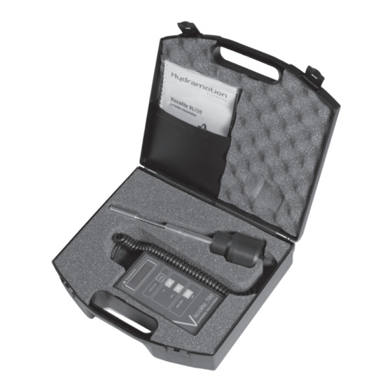
• First, inspect the contents of the carrying • First, inspect the contents of the carrying case. Immediately report any apparent shipping damage to Hydramotion Ltd or its representatives as well as to the carrier. • Please do not discard the packaging. Use •... - Page 8 (overall) L 215 (d15 model), A viscosity only 305 (d20/d21 models) All dimensions to nearest mm flexible coil lead display unit sensor probe sensor probe Hydramotion show units viscosity iscolite 700 ∅ 22 portable viscometer ∅ 15 ∅ 15 VL7-100B-d15...
-
Page 9: Fitting The Batteries
Viscolite VL7 1.3 Fitting the batteries • The Viscolite uses four 1.5V batteries, type AA or equivalent (LR6, AM 3, MN 1500). • Locate the battery compartment on the underside of the display unit (see Figure 3). • Remove the lid by pressing the part marked sliding sharply backwards. -
Page 10: Turning On
Viscolite VL7 2 Measuring viscosity 2.1 Turning on Figure 4 Display unit • Press the key on the display unit and hold it down for a second or two. • The display shows a succession of digits while the microprocessor goes through a start-up routine. -
Page 11: Measuring Viscosity
Viscolite VL7 Figure 5 Minimum immersion depths: Measuring viscosity B viscosity or temperature A viscosity only Do not clamp below here Do not clamp below here VL7-100B-d20 and VL7-100B-d21 VL7-100B-d15 2.3 Measuring viscosity • Switch on the Viscolite. • Immerse the sensor into the fluid to be measured to the depth shown in Figure 5. •... -
Page 12: Measuring Temperature
Viscolite VL7 • The viscosity reading may be noticeably higher or lower than expected if: (1) the temperature of the f luid is significantly different from that at which the reference measurement was made, or (2) the sensor is not immersed to the depths shown in Figures 1 and 5, or (3) the f luid is non-Newtonian and the reference measurement was made using a significantly different shear rate*, or (4) the fluid density is significantly higher or lower than the nominal factory setting of... -
Page 13: General Maintenance
1 in water at 20 °C. • If required, certain minor adjustments are possible, as outlined in Section 4 below (p. 20). For any other calibration problem, please contact Hydramotion Ltd or its representative for details of the Instrument Verification Service. -
Page 14: Introduction
Viscolite VL7 3 Temperature-corrected viscosity 3.1 Introduction • The Viscolite uses an internal algorithm to calculate temperature-corrected viscosity from the measured live viscosity and the measured temperature. (For more details see Appendix 1, p. 29.) • To enable temperature-corrected viscosity readings to be calculated, it is necessary for the user to enter (1) the desired reference temperature, and (2) correction factors specific to the fluid under test. -
Page 15: How To Enter An E-Format Parameter
Viscolite VL7 • Other examples: - E - FrAC Number – 04 6059 1328 0.6059132781 – 02 – 5880 0934 –58.8009340804 4362 9579 43629.5787797 *Note rounding of last digit. 3.3 How to enter an E-format parameter • Check that the Viscolite is switched on and displaying live viscosity ( ), temperature ), or temperature-corrected viscosity ( •... -
Page 16: Setting The Reference Temperature
Viscolite VL7 3.4 Setting the reference temperature • Put the instrument into Setup Mode as described in Section 3.3 (p. 15), so that “ ” is VISC showing on the display. Figure 7 Overview of the temperature-correction menu. Use the < or > keys to navigate through the sub-menus (e.g. -
Page 17: Saving Changes
Viscolite VL7 Figure 8 General functions of keys accesses a sub-menu, enables a numerical value to be changed, or fixes or burns a numerical value. move up or down through a menu or a sub-menu, or ... -
Page 18: Determination Of Correction Factors
Viscolite VL7 3.6 Determination of temperature correction factors • The correction factors are called (see p. 30). The first of these ( ) is simply an offset and can be left at zero. The factory default setting for is also zero. •... - Page 19 Viscolite VL7 (ii) Trial-and-error determination of • This method can only be used if (a) variation in fluid temperature is causing the live viscosity reading ( ) to fluctuate, (b) it is known that the temperature-corrected viscosity would be stable, i.e. truly constant, despite the fluctuations in •...
-
Page 20: Operational Adjustment
Viscolite VL7 4 Operational adjustment 4.1 Introduction • Minor operational adjustments are carried out using the Calibration and adjustment menus shown in Figure 11 (p. 21). • The following adjustments can be made: Reference Page correct small non-zero reading of viscosity in air Section 4.4 Section 4.5 stabilise reading (especially in high-noise conditions) -
Page 21: Accessing Calibration And Adjustment Menus
Viscolite VL7 4.3 Accessing calibration and adjustment menus • To access these menus from normal operating mode (“ ”, etc): (1) Bring the instrument into Setup Mode by pressing simultaneously. The display will show “ VISC ”. (2) Press . The display will show “ ”. -
Page 22: Minor Null Adjustment
Viscolite VL7 4.4 Minor null adjustment (offset) • If the reading is not zero when the sensor is perfectly clean and dry and completely surrounded by air: (1) Navigate to FCAL . (To do so from , simply press (2) Press . -
Page 23: Scale Reading By Any Desired Factor
Viscolite VL7 • To set the averaging filter: (1) Navigate to in the submenu (see Figure 11, p. 21). FCAL (2) Adjust the value as desired. (3) Navigate down the submenu to “ VLAV ” (filtered live viscosity). (4) The filtered reading can be compared with the unfiltered reading ( ) in the same submenu. -
Page 24: Take Account Of Fluid Density
Viscolite VL7 (2) Enter the appropriate conversion factor (see below). (3) If desired, save the change as described in Section 3.5 (p. 17) before switching off. Scaling from centipoise (cP) unit symbol cP equivalent conversion factor poise 0.01 poiseuille Pl (≡ Pa·s, N·s/m 1000 0.001 •... -
Page 25: Matching To Reference Instrument
Viscolite VL7 4.9 Matching to reference instrument • The Viscolite is rigorously calibrated at the factory to traceable standards using certified test fluids. • The instrument has very high repeatability. A Viscolite reading should therefore compare very well with that obtained using any other viscometer that has been properly calibrated and well maintained. -
Page 26: Calibration And Maintenance
Viscolite VL7 5 Calibration and Maintenance 5.1 Introduction • All instruments are factory-calibrated using a range of certified silicone oils. • Alternative calibration fluids can be used by special request. • Minor adjustments can be made as described above (Section 4). •... -
Page 27: Full Recalibration
Section 4. 5.3 Instrument Verification Service • Please contact Hydramotion Ltd or its representative if you wish to arrange a calibration check or require a full recalibration. • A Viscolite may be fully recalibrated: (1) to comply with quality assurance requirements, or (2) (by request) to adapt the instrument for use with a specific non-Newtonian fluid. - Page 28 England Fax number: +44 1653 693446 Telephone: +44 1653 600294 email: service@hydramotion.com If you need a copy of this Declaration, please contact Hydramotion or download a pdf www.hydramotion.com/documents.html version from the Hydramotion website page • When shipping: (1) Use the original packaging.
-
Page 29: Appendix 1: Operating Principles
Viscolite VL7 Appendix 1: Operating principles How the Viscolite determines viscosity The signal generated by the transducer is called the “ loss factor” L. It is converted to the “raw” calculated viscosity using the following polynomial equation: = (1/ + ... ) Here is the density of the fluid and , etc. - Page 30 Viscolite VL7 Viscometer matching When matching the Viscolite response to that of a reference instrument, the SPAn factor is applied (Section 4.9). The viscosity reading displayed in normal operational mode ( is then the product of the calculated viscosity , i.e. SPAn ×...
-
Page 31: Appendix 2: Menu Overview
Viscolite VL7 Appendix 2: Menu overview Item index (sub)menu item description section(s) page(s) burn save settings in non-volatile memory LCAL fl uid density t - FCAL dEGC measured temperature P30 (etc) - E - exponent of E-format number P30 (etc) FrAC fraction of E-format number P30 (etc) - Page 32 Viscolite VL7 Figure 14 Menu overview U01-04-013 R1 08/13...
-
Page 33: Troubleshooting/Alarms
— save any changes without delay to avoid loss of entered data batteries exhausted — temporary memory no longer operational dEAd no signal from transducer* *Please contact Hydramotion Ltd or its representative if you see this display. U01-04-013 R1 08/13...
Need help?
Do you have a question about the Viscolite 700 and is the answer not in the manual?
Questions and answers