Table of Contents
Advertisement
Quick Links
Advertisement
Table of Contents

Summary of Contents for Uniblitz VCM-D1
- Page 1 User Manual ® UNIBLITZ VCM-D1 Shutter Driver 14-0025 Version 2.0 2004...
- Page 2 Printed in the U.S.A. Version 2.0 2004 Vincent Associates, a Division of VA, Inc., 803 Linden Ave., Rochester, NY 14625 Tel: 585-385-5930 Fax: 585-385-6004 UNIBLITZ is a registered trademark of VA, Inc. VCM-D1 User Manual...
-
Page 3: Warranty
This warranty does not extend to cover damage resulting from alteration, misuse, negligence, abuse, normal wear and tear, or accident. VCM-D1 User Manual... - Page 4 VCM-D1 User Manual...
-
Page 5: Table Of Contents
Figure #2 – VCM-D1 Front Panel Operator Controls.............. 14 Notes .............................. 17 VCM-D1 REAR PANEL OPERATOR CONTROLS................19 Description............................ 19 Figure #4 – VCM-D1 Rear Panel Operator Controls and I/O ..........18 OPERATING BASICS ..........................21 Function Switches......................... 21 GATE INPUT ..........................21 Gate Timing Diagrams......................... -
Page 6: General Safety Summary
• Provide Proper Ventilation – To prevent product overheating, provide proper ventilation. • Do Not Operate with Suspected Failures – If you suspect there is damage to this product, have it inspected by qualified service personnel. VCM-D1 User Manual... -
Page 7: Safety Terms And Symbols
Caution statements identify conditions or practices that CAUTION could result in damage to this product or other property. These symbols appear on the equipment ATTENTION – Refer to user manual. VCM-D1 User Manual... -
Page 8: Preface
Preface This Manual provides information for the VCM-D1 Shutter Driver. The manual contains the following chapters: • Getting Started contains a brief product description, information needed to power on the drivers, fuse replacement and voltage change information, and a brief procedure to verify that it functions. -
Page 9: Getting Started
Features The UNIBLITZ VCM-D1 replaces the VMM-D1 controller for those customers requiring CE/UL/CSA certification. The VCM-D1 contains all of the features of the VMM-D1, in addition to some new features, which enhance the units’ capability in even more demanding applications. -
Page 10: Introduction
One feature of the VCM-D1 is the selection of interrupt mode. With the mode switch in the “A” position, the unit will disable itself upon an AC line loss. When power is restored, the unit will remain disabled until reset. -
Page 11: Start Up
THE POWER CORD INTO THE AC INPUT CONNECTOR REGARDLESS OF WHICH AC VOLTAGE LEVEL IS USED. 2. Check the line fuses to be sure they are the proper rating. The VCM-D1 has been shipped with the proper fuses for 115VAC operation (3AG ½ A “T” type - time-lag). -
Page 12: Voltage Change
FUSE HOLDER FUSE HOLDER SLOT FUSE #2 115V FUSE #1 (SAME POSITION OPPOSITE SIDE OF FUSE #2) COVER DOOR SLOT COVER DOOR WINDOW COVER DOOR Figure #1 - AC Input Module VCM-D1 User Manual... -
Page 13: Initial Operation And Testing
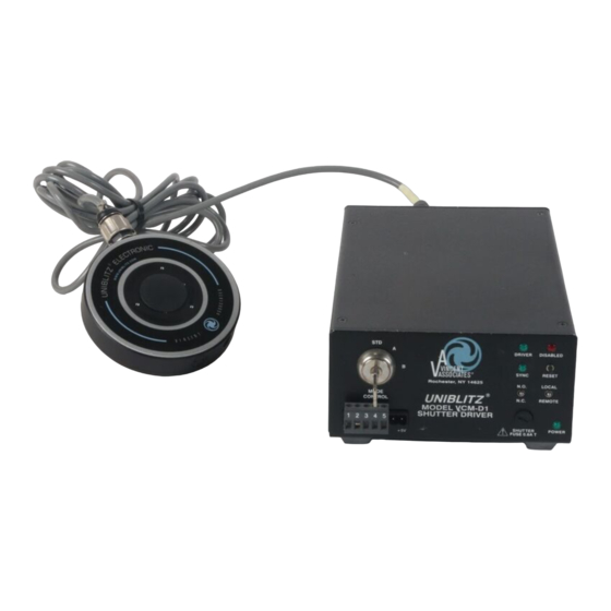
SYNC output and SYNC ACTIVE LED. The remainder of the VCM-D1 systems will not be affected. In addition the SYNC system can be disabled by sliding the “G” FUNCTION switch to the upper position. - Page 14 Figure #2 – VCM-D1 Front Panel Operator Controls VCM-D1 User Manual...
-
Page 15: Vcm-D1 Front Panel Operator Controls
CONTROL #5 Output. When interrupt is activated, this normally low output is high until reset deactivates the interrupt. CONTROL #6 AUX Output. The VCM-D1 AUX output is an active low pulse output that can be toggled TTL high and low from commands presented to the RS- 232C control input. - Page 16 10. N.O./N.C. Toggle switch. The position of this switch determines shutter status BEFORE a trigger signal is received by VCM-D1. In the N.C. position the shutter will be activated open by an input pulse signal. In the N.O. position the shutter will be activated closed. The N.O./N.C switch acts to invert the shutter operation.
-
Page 17: Notes
Notes VCM-D1 User Manual... - Page 18 Figure #4 – VCM-D1 Rear Panel Operator Controls and I/O VCM-D1 User Manual...
-
Page 19: Vcm-D1 Rear Panel Operator Controls
VCM-D1. Therefore, this input can be used to “pick” a pulse or pulses from a series of trigger pulses presented to the TRIGGER INPUT. This input must be used in conjunction with the TRIGGER INPUT. - Page 20 11. PULSE OUTPUT BNC. The duration of this pulse is equal to the duration of the shutter exposure pulse. This output can be used to daisy chain VCM-D1 units together. A TTL exposure pulse input to the PULSE INPUT BNC will appear at the PULSE OUTPUT BNC. Note toggling the N.O./N.C.
-
Page 21: Operating Basics
TRIGGER INPUT is selected to the active low state (function switch “A” down position). When a stream of trigger pulses is input to the TRIGGER INPUT and the GATE INPUT is in the high state (TTL logic “1”, +5V), the trigger signals will operate the VCM-D1 as described in the VCM-D1 User Manual... -
Page 22: Gate Timing Diagrams
(See Figure #5B.) Therefore, the number of trigger pulses input (or GATE INPUT duration) is equal to the trigger period times the number of exposures desired. The VCM-D1 TRIGGER INPUT opens the shutter with the first pulse presented to the input and closes the shutter on the subsequent pulse. -
Page 23: Mode Selection
The key can be removed in any position thus preventing the switch from inadvertently being changed while in operation. This will ensure that if an interrupt is set, the shutter will not return to its original state until the VCM-D1 unit is reset (by any of a number of methods). -
Page 24: Rs-232C Operation
All other pins not used. Be sure to connect the Tx pin, Pin 3 from the IBM 9-Pin D-Sub (or Pin 2 from the 25-Pin D-Sub) male connector to the Rx pin, Pin 5 of the VCM-D1 RJ-45 INPUT connector (located at the rear panel) for proper operation. Connect all other functions as indicated above. - Page 25 The following is a test program written to test the input commands to the RS-232 interface of the VCM-D1 controllers. (This program and LabView programs (not listed) are available by downloading from the resource section of our web site (www. UNIBLITZ .com), request via e-mail (vincentassociates@ UNIBLITZ .com), or calling (800) 828-6972.) Other programs...
-
Page 26: Rs-232 Test Program
ELSEIF A$ = "E" OR A$ = "e" THEN PRINT #1, CHR$(J + 4); PRINT "ENABLE AUX COMMAND SENT" GOSUB TIMEOUT GOTO MENU ELSEIF A$ = "D" OR A$ = "d" THEN PRINT #1, CHR$(J + 5); PRINT "DISABLE AUX COMMAND SENT" VCM-D1 User Manual... - Page 27 J = 224 C$ = "6" ELSEIF B$ = "7" THEN J = 240 C$ = "7" ELSE J = 64 C$ = "X" END IF PRINT "STARTING ASCII DECIMAL # = ", J GOSUB TIMEOUT CLS 0 RETURN VCM-D1 User Manual...
-
Page 28: Shutter Frequency Of Operation
VS25 shutter (with Teflon shutter blades) has a minimum exposure pulse of 6ms, if the exposure or pulse width presented to the VCM-D1’s PULSE INPUT is less than 6ms, the shutter may not open fully. If the unit still does not operate properly, when using the proper pulse width, please notify Vincent Associates immediately. -
Page 29: Pulse Voltage Graphs
5 msec. 50.0 40.0 30.0 msec. msec. msce. msec. msce. 20.0 msec. msec. 10.0 10.0 13.3 15.0 17.2 20.0 22.0 25.0 30.0 35.0 40.0 45.0 50.0 55.0 60.0 65.0 70.0 Frequency Figure #8 Pulse Voltage vs. Frequency VCM-D1 User Manual... - Page 30 Figure #9 Overall VCM-D1 Dimensions VCM-D1 User Manual...
-
Page 31: Maintenance
Proper care and maintenance of the unit should be taken as with any electronic instrument. Inspection and Cleaning Inspection and cleaning describes how to inspect and clean the VCM-D1 . Inspection and cleaning are preventative maintenance. Preventative maintenance, when done regularly, may prevent driver malfunction and enhance its reliability. -
Page 32: Inspection - Exterior
– no user serviceable parts inside. Cleaning Procedure - Exterior 1. Remove loose dust on the outside of the VCM-D1 with a lint free cloth. 2. Remove remaining dirt with a lint free cloth dampened in a general purpose detergent-and-water solution. -
Page 33: Specifications
TRIGGER Input; maximum pulse width determined by multiple of TRIGGER signal period; TTL compatible: minimum high-level +2.0 VDC, maximum low- level +0.8 VDC; sink current 1µA. Located on rear panel. VCM-D1 User Manual... - Page 34 1K ohms; maximum source current 5 mA; maximum sink current 100 mA; maximum low-level +0.5 VDC, minimum high-level +4.5 VDC. Duration time determined by width of active pulse applied to applicable PULSE Input. Located on rear panel. VCM-D1 User Manual...
- Page 35 RS-232C OUTPUT Baud rate 9600, 8 Data bits, 1 Stop bit, No Parity, No flow control. (Dual RJ45) This output provided for daisy-chain application of up to 8 VCM-D1 (or VMM series) controllers. Located on rear panel. AUX Out Active-low only; source impedance 1K ohms; maximum source...
- Page 36 Two ¼ Amp "T" slow blow (3AG ¼ x 1¼") for 230 VAC line One 0.6 Amp "T" slow blow (5 x 20mm) for Shutter coil (See page 11 "Line Fuse Replacement" instructions for AC power fuse change) VCM-D1 User Manual...
- Page 37 910RJF female DB9 to RJ45 adapter (used with 810RJ and PC) 910RJM male DB9 to RJ45 adapter (used with 810RJ & VMM driver) 810RS RS-232C/RS-422 interconnect serial cable (MAC with Din8) LVD96 TTL/LVDS signal converter (CAMELIA camera) VCM-D1 User Manual...
- Page 38 APPLICABLE CERTIFICATIONS (The VCM-D1 has successfully completed and is compliant with the following tests performed at MET Laboratories, Inc.) Name Description Safety Certification – UL / CSA Application of Council Directive(s): LVD 73/23/EEC as amended by / CE 93/68/EEC Standards to which Conformity is Declared: EN61010-1 EMC Certification –...
-
Page 39: Index
DISABLED Indicator, 16 DRIVER ACTIVE LED, 16 N.O./N.C. switch, 13, 16, 23 Notes, 17 VCM-D1, 1, 8, 9, 10, 11, 13, 14, 15, 16, 19, 20, 21, 23, 24, 25, 28, 31 Voltage Change, 12 exposure interval, 19 open command, 16, 19, 23, 24...
Need help?
Do you have a question about the VCM-D1 and is the answer not in the manual?
Questions and answers