
Summary of Contents for GeoCue TrueView 535
- Page 1 GeoCue 4/19/2023 Version 1.0 TrueView 535 Hardware User Guide Compatible with LP360 version 2023.1.25. and newer. 4/19/2023...
-
Page 2: Table Of Contents
Notice To Users............................8 Warnings ............................. 8 Disposal .............................. 9 Overview............................... 10 TrueView 535 Payload System Items ....................10 TrueView 535 Product Specifications ....................11 Camera Product Specifications ..................... 12 TrueView 535 Payload Technical Specifications................13 System Description ..........................15 TrueView 535 Payload Parts ...................... - Page 3 TrueView 535 Hardware User Guide TrueView 535 Payload Field Operations ....................29 Base Station ............................29 Pre-Flight ............................30 Disable Obstacle Avoidance ......................30 Center of Gravity (GC) Calibration ....................31 LED Status Indicators Operation ....................31 Heading Alignment Maneuver....................... 32 After Landing ............................
-
Page 4: About Geocue
LiDAR processing tools in North America and LP360 is the world’s most widely used tool for exploiting point cloud data. In 2014, GeoCue started a division focused on using small Unmanned Aerial Systems for high accuracy mapping. Leveraging our expertise in... -
Page 5: About Lp360 Drone
TrueView 535 Hardware User Guide ABOUT LP360 DRONE LP360 is a 64-bit Windows® desktop application used for many years by the LP360 Geospatial community for processing traditional aerial, mobile, and terrestrial tripod laser scanner data. The LP360 Drone community is the focus of this Users Guide containing the LP360 workflows for processing and exploiting TrueView, microdrones®... -
Page 6: About Trueview Reckon
Management and automatic delivery of sensor calibration files • Automatic sensor health check • Transfer of sensor Cycle data to GeoCue for technical support • Management of TrueView Points for services that are paid via a metering scheme (marked in this list with $T) •... -
Page 7: Fcc And Ic Compliance
20953-RPI4B 2ABCB-RPI4B model B model B model B APPLANIX APX- Please see Please see 15 /20 Manufacturer Manufacturer Compliance Compliance Certificate Certificate Hesai PandarXT-32 Please see 2ASO2PANDARX Manufacturer Compliance Certificate Table 1. Radio components in the TrueView 535 payload. 4/19/2023... -
Page 8: Notice To Users
Before you use your TrueView 535 payload please read these warnings carefully. Failure to do so can result in serious injury. Do not attempt to take apart, reassemble, or alter the TrueView 535 payload as it will void the warranty. Only qualified personnel can service the payload. -
Page 9: Disposal
TrueView 535 Hardware User Guide This device requires adequate airflow to prevent overheating during operation. Do not use this device for prolonged periods without proper ventilation or airflow. Inadequate ventilation can cause the device to overheat, leading to malfunctions, damage, or even fire. -
Page 10: Overview
TrueView 535 Hardware User Guide OVERVIEW TrueView 535 Payload System Items Quantity Item TrueView 535 payload TrueView 535 payload travel case 32GB UMS flash drive (Only use the UMS flash drives provided) (1) (2) AV18 GPS antenna LiDAR calibration report... -
Page 11: Trueview 535 Product Specifications
TrueView 535 Hardware User Guide TrueView 535 Product Specifications Model TrueView 535 payload Article number – TrueView 535 PLD1001145A00T Year of release 2023 Mass 1.6 kg Dimensions 294x185x195 (mm) Table 3. TrueView 535 payload product specifications. 4/19/2023... -
Page 12: Camera Product Specifications
5472 x 3648 Pixel Size: H x V (µm) 2.41 Sensing Area: H x V (mm) 13.2 x 8.80 Focal Length 10.6 mm FOV (individual camera) 63.8° FOV (Combined lateral view cameras) 120° Table 4. TrueView 535 payload camera product specifications. 4/19/2023... -
Page 13: Trueview 535 Payload Technical Specifications
(1) Flight Altitude Above Ground Level (AGL) (2) Area coverage is computed for an example of a 20-minute survey (3 minutes for take-off and landing) at a drone speed of 5 m/s at 56° Field of View (FOV) Table 5. TrueView 535 payload technical specifications. 4/19/2023... -
Page 14: Figure 1. Average Point Density Vs Speed For Given Agl (Altitude) (Single Pass, 1St Return Only)
TrueView 535 Hardware User Guide Figure 1. Average point density vs speed for given AGL (altitude) (single pass, 1st return only). Figure 2. Coverage (acres/hour) vs AGL (altitude) for given overlap. 4/19/2023... -
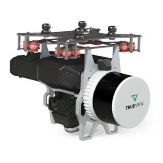
Page 15: System Description
TrueView 535 Hardware User Guide SYSTEM DESCRIPTION This section describes the TrueView 535 payload. It addresses how it works, how to set it up, and how to configure the system. Figure 3. TrueView 535 payload. 4/19/2023... -
Page 16: Trueview 535 Payload Parts
1. Cooling vents (right and left side) 2. Payload interface 3. Scanner 4. USB port 5. Multifunction button 6. LED status indicators 7. Battery compartment 8. Debug port 9. Three (3) GeoCueMapping cameras Table 6. Explanation of TrueView 535 payload parts. 4/19/2023... -
Page 17: Usb Port
Figure 5. USB port located on the rear left side of the payload. UMS Drive The TrueView 535 payload includes one approved UMS drive with the capacity of 32GB flash storage that guarantees a maximum transfer speed over USB3 technology while minimizing electromagnetic radiation. -
Page 18: Multifunction Button
TrueView 535 Hardware User Guide Multifunction Button The multifunction button can be used to start/stop data collection or to abort an operation following the combinations below: Button Press Type Payload Reaction LED Readout SYS LED will switch to a slow... -
Page 19: Debug Port
The debug port is located on the bottom right side of the payload. To access it remove the plastic cover. The debug port is used for service and advanced configuration of the TrueView 535 payload. Do not use the debug port unless instructed to by GeoCue Customer Support. -
Page 20: Led Status Indicators
The LED status indicators provide signals to alert the user of the payload state or errors. Further information can be retrieved through the web interface. Once the power is turned on, there are a total of two LED status indicators on the front of TrueView 535 payload to display the payload status. -
Page 21: Table 8. Led Status Indicators Chart
TrueView 535 Hardware User Guide Table 8 shows all the lighting sequences, LED messages, and their meanings. Table 9 shows how to interpret the symbols in the table. LED Readout Meaning No light No power Slow blink Payload is starting... -
Page 22: Procedures
Clean the connectors and pegs with dry compressed air if dirt or debris is present. Do not connect the payload if the connectors or pegs are damaged, or if dirt or debris cannot be removed. Damage to the payload or drone can occur. Contact GeoCue Customer Service for more assistance. CAUTION... -
Page 23: Figure 12. Orange Safety Arrows On The Payload Adapter Clip (Open Position)
TrueView 535 Hardware User Guide Figure 12. Orange safety arrows on the payload adapter clip (open position). 3. Align the front of the payload with the front of the drone. See Figure 11 for front orientation. 4. Push the payload up into the adapter slot. Make sure all four pegs are flush with the mount. -
Page 24: Release The Payload From The Drone
TrueView 535 Hardware User Guide Figure 14. Make sure the payload clips are in the fully retracted position. Confirm that there are no orange arrows showing on the adapter clip. If the locking mechanism does not fully engage, remove, and reattach the payload. Light pressure can be applied to the payload and the lock plate to help engage the locking mechanism. -
Page 25: Figure 15. Release The Payload Adapter Clip
TrueView 535 Hardware User Guide Figure 15. Release the payload adapter clip. Before releasing a payload to attach another payload make sure that the drone and the payload are fully powered OFF. CAUTION 4/19/2023... -
Page 26: Additional Payload Operation
TrueView 535 Hardware User Guide ADDITIONAL PAYLOAD OPERATION Cleaning As with most optical surfaces, minimal cleaning is the best practice. Any contamination, dust, or debris on the scanner optical surfaces can cause the laser light to diffuse or weaken. This will result in poor data collection. -
Page 27: Scanner And Camera Lens/Sensor Care
TrueView 535 Hardware User Guide Scanner and Camera Lens/Sensor Care When the payload is not being used, it is recommended to install the scanner and camera lens covers. Do not leave the scanner or camera pointing directly towards the sun. This can cause damage to the sensors. -
Page 28: Firmware Update
Once completed power off the drone battery. Verification of the update: Remove the UMS storage device from the TrueView 535 payload and insert it into the computer. Navigate to the UMS storage device drive and verify the file extensions was changed to .installed on every .mdpkg and .json file. -
Page 29: Trueview 535 Payload Field Operations
TrueView 535 Hardware User Guide TRUEVIEW 535 PAYLOAD FIELD OPERATIONS 515vB Field Operations Base Station The TrueView 3DIS records GNSS signals during flight which will be corrected later in EVO. This type of system is known as a PPK system. Base station processing methods should be considered during the planning process because the user will need to determine how they plan to correct their flight data before collecting. -
Page 30: Pre-Flight
TrueView 535 Hardware User Guide Pre-Flight DISABLE OBSTACLE AVOIDANCE IMPORTANT M300 Only The integration of the TrueView 3DIS system will cause disruption to the M300’s built-in obstacle avoidance detection systems. If these systems are not disabled, they can cause erratic and potentially dangerous behavior including loss of control of the drone. -
Page 31: Center Of Gravity (Gc) Calibration
TrueView 535 Hardware User Guide CENTER OF GRAVITY (GC) CALIBRATION IMPORTANT M300 Only When heavy payloads are carried on the M300 platform a center of gravity (GC) calibration must be performed if there is any change to the payload. This would include if you switched from a TrueView 410 to a TrueView 515 or DJI P1 or even switched to flying without a payload. -
Page 32: Heading Alignment Maneuver
TrueView 535 Hardware User Guide HEADING ALIGNMENT MANEUVER The heading alignment maneuver needs to be done after takeoff, before flying the mission, and after the mission prior to landing for each flight. This maneuver is critical for getting accurate heading corrections for the IMU and will impact the results of the data if not performed. -
Page 33: After Landing
TrueView 535 Hardware User Guide On windy days, avoid starting the maneuver into a headwind, as the drone may not be able to achieve accelerations that are high enough. Try doing the maneuver crosswind if possible. NOTE Figure 19. Heading alignment maneuver. -
Page 34: Trueview Mission Checklist
If SYS LED turns to blinking or solid red, it is safe to turn off and move to troubleshoot section or contact GeoCue for further instructions. Remove UMS drive and pass to post-processing. -
Page 35: Support
Normal support business hours are Monday - Friday, 8 AM — 5 PM USA Central Time. Our GeoCue Support website contains general workflow information, in addition to specific issue and error messages that you may encounter. Click on the link and search for information contained in the knowledge base. -
Page 36: List Of Tables
TrueView 535 Hardware User Guide LIST OF TABLES Table 1. Radio components in the TrueView 535 payload................7 Table 2. List of TrueView 353 payload system items.................. 10 Table 3. TrueView 535 payload product specifications................11 Table 4. TrueView 535 payload camera product specifications..............12 Table 5.
Need help?
Do you have a question about the TrueView 535 and is the answer not in the manual?
Questions and answers