Table of Contents
Advertisement
Quick Links
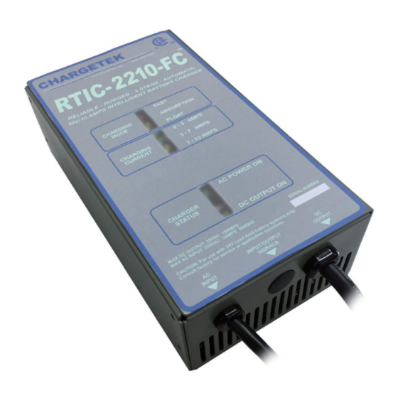
Charger operation
The RTIC-2210-FC is fully automatic once installed properly.
The LED indicator lights inform the user of the progress of the
charging cycle and confirm proper connections.
Electrical characteristics
PARAMETER DESCRIPTION / CONDITIONS
MIN
NOM
V
Fast charge voltage, 25C
28.8
29.0
FSTERM
V
Float voltage, I
< 1.0 A, 25C
26.4
26.8
FLOAT
OUT
I
Fast charge, V
= 12V
10
11
FS
BATTERY
I
Float charge termination current
1.6
1.7
FLTERM
V
RMS AC voltage range
90
120
AC
I
Standby current, AC off
SBY
LED indicators
Charging mode: Indicates the state of charge of the battery.
The green Float light indicates the battery is fully charged.
Charging current LEDs indicate amount of current.
AC Power On LED indicates AC power is applied to the
charger.
Charging status LED indicates the output is connected
properly to the battery and is being charged.
Outline and mounting
Dimensions in inches
LIMITED WARRANTY
For two years from date of purchase, Chargetek Inc. will at its discretion repair or replace for the original consumer, free of
charge, any part or parts found to be defective by Chargetek in workmanship or material. All shipping charges under this
warranty must be paid by the consumer. Proof of purchase is required.
There is no other expressed warranty. Implied warranties, including those of merchantability and fitness for a particular
purpose are limited to two years from the date of purchase. This is the exclusive remedy and consequential damages are
excluded where permitted by law.
Rev: 3/18/16
Protection modes
Over temperature: The unit inhibits until it cools off and then
restarts automatically. This is indicated by the AC Power and
Float LEDs flashing. In very high ambient temperatures, it is
possible for the non-auto reset thermal protection to activate.
This is indicated by the AC Power on and 14-20 Amp Charging
Current LEDs flashing. If this occurs, the AC power should be
disconnected and reconnected once the charger has cooled off.
MAX
UNITS
Over voltage: Activates in the event of a regulation malfunction
and inhibits the charger. An over voltage condition is indicated
29.1
VDC
by the AC Power On and Fast LEDs flashing. If the over voltage
persists, the factory should be consulted.
27.2
VDC
Optional relay contacts
12
Amps
1.8
Amps
Up to four relay contacts are provided depending upon the op-
tion purchased. The relay specification is available on our web
132
VAC
page. Please observe relay specifications in order to maintain
proper operation.
0.5
ma
Optional temperature compensation
The temperature compensation pod can be tie-wrapped to the
charger cable in the immediate vicinity of the battery or wall
mounted. Standard compensation is 15mV-18mV per degree
Celsius per cell or factory programmable upon request.
Optional signal connector
PIN NUMBER
SIGNAL
DESCRIPTION
2,8
AC Fail
AC < 85VAC
3,9
DC High
DC > 15.5VDC
4,10
DC Low
DC < 6VDC
1,7
Charger Fail
Unit failed
11
TC Data
Temp sense data line
12
TC Rtn
Temp sense bias rtn
6
TC Bias
Temp sense bias power
RTIC-2210-FC
Installation Manual
Please read the entire installation manual before installing
the battery charger. If there are any questions or concerns,
please email us or call our toll-free number given below.
The RTIC-2210-FC is a rugged, fan cooled and sophisti-
cated three state lead-acid battery charger. With a wide
operating temperature range and UL/CSA1012 certifica-
tion, this product is especially suited for high end industrial
applications and severe environments.
The RTIC-2210-FC is factory programmable to accom-
modate several charging algorithms, an LED display to
indicate status, and optional four relay contacts to indicate
Chargetek
3639 E. Harbor Blvd. Suite 203G Ventura, CA 93001 ~ Phone: (866) 482-7930 ~ Fax: (805) 482-7936
www.chargetek.com
various scenarios. Temperature compensation is imple-
mented digitally allowing accurate and noise free sensing
up to a distance of 300 feet eliminating problems associ-
ated with conventional analog solutions.
The charging algorithm, LEDs, and relay control signals
are generated by an embedded microcontroller that con-
tains software developed by and proprietary to Chargetek.
The RTIC-2210-FC precisely controls charging voltage
and current to ensure a complete recharge every time.
The charger may be left connected indefinitely to the bat-
tery, maintaining a full charge.
Advertisement
Table of Contents

Related Manuals for Chargetek RTIC-2210-FC


Summary of Contents for Chargetek RTIC-2210-FC
- Page 1 For two years from date of purchase, Chargetek Inc. will at its discretion repair or replace for the original consumer, free of charge, any part or parts found to be defective by Chargetek in workmanship or material. All shipping charges under this warranty must be paid by the consumer.
- Page 2 Incorrect reassembly may result AC wire connections in an electrical shock or fire. The RTIC-2210-FC is equipped with a factory installed 6 foot Stage 1: Constant current or bulk charge mode Become familiar with all instructions, specifications and AC cord with a ground connection.
Need help?
Do you have a question about the RTIC-2210-FC and is the answer not in the manual?
Questions and answers