Table of Contents
Advertisement
Quick Links
This installation applies only to: 51.2V-100Ah LFP-LV Module
www.powersyncenergy.com
(877) 459-4591
© 2022 POWERSYNC Energy Solutions, LLC
01/10/23
LFP-LV MODULE
PRODUCT MANUAL
48V-100Ah LFP-LV Module
25.6V-200Ah LFP-LV Module
COMPLIANCE:
Certifications: UL-1973, CE, IEC62619 & CB, KC BIS
Shipping Class: UN3480, Class 9, UN38.3
LFP-LV Module Product Manual
1
Advertisement
Table of Contents

Summary of Contents for PowerSync LFP-LV
- Page 1 LFP-LV MODULE PRODUCT MANUAL This installation applies only to: 51.2V-100Ah LFP-LV Module 48V-100Ah LFP-LV Module 25.6V-200Ah LFP-LV Module COMPLIANCE: Certifications: UL-1973, CE, IEC62619 & CB, KC BIS Shipping Class: UN3480, Class 9, UN38.3 www.powersyncenergy.com (877) 459-4591 LFP-LV Module Product Manual © 2022 POWERSYNC Energy Solutions, LLC 01/10/23...
-
Page 2: Table Of Contents
ENCLOSURE INFORMATION 3. 1. Grounding Instructions 3. 2. Leveling Instructions 3. 3. Installation Instructions – General SECTION 4. BATTERY INSTALLATION 4. 1. Safety Check 4. 2. Module to Module Connections 4. 3. Sample Multi Stack Line Diagram 4. 4. Improper Connection Methods SECTION 5. MODULE COMMUNICATION SETTINGS 5. 1. 6-BIT MODULE COMMUNICATION SETTINGS 5. 2. 8-BIT MODULE COMMUNICATION SETTINGS 5. 3. RJ485 CONNECTOR DIAGRAM 5. 4. 8Bit Toggle Switch Settings www.powersyncenergy.com (877) 459-4591 LFP-LV Module Product Manual © 2022 POWERSYNC Energy Solutions, LLC 01/10/23... - Page 3 SECTION 6. SYSTEM SETUP 6. 1. Best Practices 6. 2. Sol-Ark 6. 3. SMA Sunny Island 6048 6. 4. Outback Radian 8048 SECTION 7. TROUBLESHOOTING 7. 1. LED light Indications SECTION 8. MODULE PACKAGING SECTION 9. LFP-LV MODULE LIMITED WARRANTY www.powersyncenergy.com (877) 459-4591 LFP-LV Module Product Manual © 2022 POWERSYNC Energy Solutions, LLC 01/10/23...
-
Page 4: Safety Information
NOT CONNECT A 6-BIT BATTERY TO AN 8-BIT BATTERY DO NOT CONNECT ANY POWERSYNC MODULE TO ANY OTHER BRAND OF BATTERY DO NOT CONNECT GEN 3 POWERSYNC MODULES WITH GEN 2 OR GEN 1 POWERSYNC MODULE 1. 3. ABOUT THIS INSTALLATION MANUAL •... -
Page 5: Symbols Used In This Manual
1. 4. SYMBOLS USED IN THIS MANUAL WARNING Important safety information to follow. Recycle or dispose of Lithium batteries in accordance with local Laws/regulations. Do not dispose of battery in a fire! Do not dispose of battery in the trash! NOTE: Do not dispose of battery in the trash! www.powersyncenergy.com (877) 459-4591 LFP-LV Module Product Manual © 2022 POWERSYNC Energy Solutions, LLC 01/10/23... -
Page 6: Warnings
DO NOT connect the battery modules in series. (Parallel connections only.) DO NOT connect POWERSYNC 51.2V-100Ah modules with 25.6V-200 Ah or 12.8V-400Ah modules. Batteries must be connected with batteries of the same voltage and capacity. DO NOT open the battery case or disassemble the battery. -
Page 7: Before You Start
• Knowledge of the functional principles and operation of on-grid and off-grid (backup) systems. • Knowledge of the dangers and risks associated with installing and using electrical devices and acceptable mitigation methods. • Knowledge of the installation of electrical devices • Knowledge of and adherence to this guide and all safety precautions and best practices. 1. 7. BEFORE INSTALLATION: • Remove any possible metallic items that may be at risk of an electrical short such as jewelry, watches, pens, metal bars, or frames. • All tools must be insulated The POWERSYNC LiFePO4 Battery modules are shipped between 10% and 50% Depth of Discharge (“DOD”). Prior to opening the battery module box(es), inspect all boxes to ensure that there is no damage during shipping. If a box is damaged document the damage with pictures. If the damage is significant do not open the box. Contact POWERSYNC at (877) 459-4591 to schedule a return of the module to POWERSYNC. If long term battery storage is necessary, please charge and discharge the battery at least once every three months to ensure the best performance. The optimal state of charge for storage is between 50% and 60% DOD. Please use the battery in the temperature range which defined in the manual. 1. 8. SYSTEM COMPATIBILITY POWERSYNC modules are compatible with a wide range of 3rd party inverters, solar charge controllers, and rectifiers. Always consult the installation manuals of ancillary products prior to installation. www.powersyncenergy.com (877) 459-4591 LFP-LV Module Product Manual © 2022 POWERSYNC Energy Solutions, LLC 01/10/23... -
Page 8: Safety Check
* Do not short-circuit, over-char e,or over discharge the battery 58.4V * Do not disassemble or modify the battery * Do not expose the battery to heat,flame,water * Do not reverse the polarity of the battery CERTIFIED TO ANSI/CAN/UL STD.1973 www.powersyncenergy.com (877) 459-4591 LFP-LV Module Product Manual © 2022 POWERSYNC Energy Solutions, LLC 01/10/23... -
Page 9: Battery Information
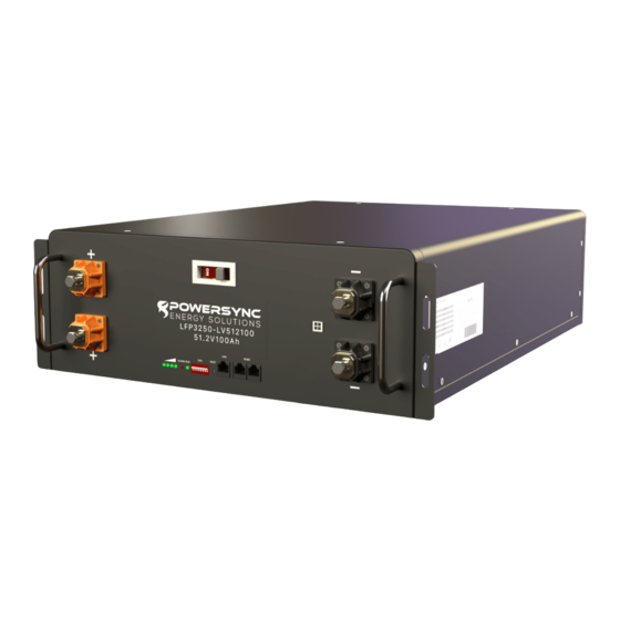
Cell Smallest subpart of an electrochemical LFP-LV Module that stores the chemical energy Module Aggregation of several cells or blocks Stack Aggregation of up to up to 16 modules Battery system Parallel connection of several packs or strings forming the battery BMS Battery Management System C-Rate The C-Rate is the rate of discharge relative to the capacity of the battery. When multiple POWERSYNC battery modules are connected in parallel, the maximum C-Rate of the battery is 2C (200ADC) per module. There is a 400A rated internal busbar between the top and bottom terminals on the inside of the battery for both the positive and negative connections. For best cycle life, the recommended normal operating C-Rate is 0.3C. For more information review the “Normal Performance Parameters” section of this manual. Dual positive and negative terminals for fast and easy connectivity. No external bus bars are necessary. 250A full stop breaker 3. SOC Meter Run / Alarm Lights Toggle Switches Reset Button (To Reset BMS) 7. CAN 2.0B Active (29bit ID) Protocol (Battery to Inverter) RS485 Connector (Module to Module Communications) 9. RV-C Communication Port 10. Module to Module connector (Supplied Separately) www.powersyncenergy.com (877) 459-4591 LFP-LV Module Product Manual © 2022 POWERSYNC Energy Solutions, LLC 01/10/23... -
Page 10: Module Specifications: 51.2V-100Ah And 48V-100Ah
54.75V (<51V) MECHANICAL SPECIFICATIONS Case 19” 4U Stainless Steel Protection Rating IP20 Dimensions 19 x 24 x 6.3 in. 19 x 20 x 6.3 in. 19 x 24 x 6.3 in. 19 x 20 x 6.3 in. (W x D x H) 482 x 610 x 160 mm 482 x 525 x 160 mm 482 x 610 x 160 mm 482 x 525 x 160 mm Weight ±116 lbs (52.6 kg) ±108 lbs (49 kg) ±116 lbs (52.6 kg) ±108 lbs (49 kg) ENVIRONMENTAL SPECIFICATIONS Oper. Temp. -10°C to 60°C (14°F to 140°F) Warranty 15 Year Limited Certifications UL-1973, CE, IEC62619 & CB, KC BIS Shipping UN3480, Class 9, UN38.3 www.powersyncenergy.com (877) 459-4591 LFP-LV Module Product Manual © 2022 POWERSYNC Energy Solutions, LLC 01/10/23... -
Page 11: Module Specifications: 48V-100Ah
13.75V Over Voltage (Recovery) 29.2V (<27V) 14.6V (<13.5V) MECHANICAL SPECIFICATIONS Case 19” 4U Stainless Steel Protection Rating IP20 Dimensions 19 x 24 x 6.3 in. 19 x 20 x 6.3 in. 19 x 24 x 6.3 in. (W x D x H) 482 x 610 x 160 mm 482 x 525 x 160 mm 482 x 610 x 160 mm Weight ±116 lbs (52.6 kg) ±108 lbs (49 kg) ±116 lbs (52.6 kg) ENVIRONMENTAL SPECIFICATIONS Oper. Temp. -10°C to 60°C (14°F to 140°F) Warranty 15 Year Limited Certifications UL-1973, CE, IEC62619 & CB, KC BIS Shipping UN3480, Class 9, UN38.3 www.powersyncenergy.com (877) 459-4591 LFP-LV Module Product Manual © 2022 POWERSYNC Energy Solutions, LLC 01/10/23... -
Page 12: Product Diagram
2. 4. PRODUCT DIAGRAM 18.97 in / 482 mm 18.30 in / 465 mm 17.32 in / 440 mm 2.36 in 6.29in 60 mm 160mm 24 in 610 mm www.powersyncenergy.com (877) 459-4591 LFP-LV Module Product Manual © 2022 POWERSYNC Energy Solutions, LLC 01/10/23... -
Page 13: Enclosure Information
3. 2. LEVELING INSTRUCTIONS Prior to loading any equipment into the enclosure put the levelers down and make sure that the enclosure is level. Do not move rack with equipment installed 3. 3. INSTALLATION INSTRUCTIONS – GENERAL Prior to loading any battery modules, ensure that the enclosure is capable of supporting the entire weight of all battery modules. The approximate weight of each battery modules is 108 lbs. Provide the minimum spacing between the accessories/components and the housing that shall be maintained for safe operation of the equipment when installed in accordance with the National Electric Code, ANSI/NFPA 70. 3. As appropriate, all wiring and equipment should be installed in accordance with NFPA 70, “National Electrical Code,” and the applicable sections of ANSI C2, “National Electrical Safety Code.” The equipment shall be installed by trained service personnel. All parts such as screws, bolts, wiring and similar parts that are required to complete the assembly shall be provided. Assembly instructions shall be provided in the Installation Instructions. Prior to loading any equipment into the rack use levelers to level the enclosure. When installing battery modules install from the lowest rack space first. Do not install from the top down. www.powersyncenergy.com (877) 459-4591 LFP-LV Module Product Manual © 2022 POWERSYNC Energy Solutions, LLC 01/10/23... -
Page 14: Battery Installation
WHEN MORE THAN ONE MODULES ARE CONNECTED USING THE TERMINAL TO TERMINAL CONNECTIONS AS DESCRIBED IN SECTION 4.3.2, CURRENT CAN FLOW FROM MODULE TO MODULE IF ONE OF THE MODULE BREAKERS IS IN THE ON POSITION 3. Select the appropriate Personal Protective Equipment “PPE” according to your hazard analyses. Select the appropriate tools according to the chosen hardware. ALWAYS USE INSULATED TOOLS. www.powersyncenergy.com (877) 459-4591 LFP-LV Module Product Manual © 2022 POWERSYNC Energy Solutions, LLC 01/10/23... -
Page 15: Module To Module Connections
2/0 welding cable for the module to module connections. The module that is connected to the inverter is always the “HOST” module. It is recommended to connect the batteries as seen in Figure 2. Connect the P1 terminal on the host module to the positive terminal on the inverter. The the N1 terminal of the HOST can be connected to the negative terminal on the inverter. Alternatively, the N2 terminal on the last module in the stack can be connected to the negative terminal on the inverter. Starting with the Host battery, connect the P-2 terminal on the Host battery with the P-1 terminal on Sub Module 1. Connect the N2 terminal on the Host battery with the N-1 terminal on Sub Module 1. 3. REPEAT for each battery module up to the last module in the rack. FIGURE 2. MODULE TERMINAL CONNECTIONS www.powersyncenergy.com (877) 459-4591 LFP-LV Module Product Manual © 2022 POWERSYNC Energy Solutions, LLC 01/10/23... - Page 16 4. 2. 3. CAN BUS PORT CONNECTION The can-bus port on the HOST battery shall be connected with the corresponding connection to the CAN bus on the PCS/inverter as seen with the BLUE drawing in Figure 3. Once all connections have been completed program the module toggle switches according to section “Section 5. Module Communication Settings” on page 19. 4. 2. 4. RS485 CONNECTIONS There are two RS485 connectors on each module for module to module connections. When connecting the communications cables they shall be connected as seen by the black cables drawing in Figure 3. Continue down the string with alternating port connections. FIGURE 3. MODULE TERMINAL CONNECTIONS www.powersyncenergy.com (877) 459-4591 LFP-LV Module Product Manual © 2022 POWERSYNC Energy Solutions, LLC 01/10/23...
-
Page 17: Sample Multi Stack Line Diagram
4. 3. SAMPLE MULTI STACK LINE DIAGRAM When using the 6-Bit battery modules, up to 62 modules can be connected in parallel. When using the 8-Bit modules, up to 16 batteries canbe connected in parallel. It is recommended that each stack should have an equal number of batteries. When connecting multiple stacks of batteries in parallel, it is recommended to connect each stack to a common DC bus or a fused combiner box as seen in Figure 4. Contact POWERSYNC for additional support For RS485 communications all batteries will be connected as one string in a daisy chain format from the Host to the last module in the system. FIGURE 1. SAMPLE MULTI-STACK 62 MODULE DIAGRAM Fused Battery Combiner Battery Negative to Inverter Battery Positive to Inverter Communications RS485 to Inverter Stack 1 Stack 2 Stack 3 ~ 61 Stack 62 www.powersyncenergy.com (877) 459-4591 LFP-LV Module Product Manual © 2022 POWERSYNC Energy Solutions, LLC 01/10/23... -
Page 18: Improper Connection Methods
4. 4. IMPROPER CONNECTION METHODS DO NOT REVERSE POLARITY BY CONNECTING DO NOT CONNECT MODULE TO MODULE USING A POSITIVE TERMINALS TO NEGATIVE TERMINALS SINGLE TERMINAL CONNECTION www.powersyncenergy.com (877) 459-4591 LFP-LV Module Product Manual © 2022 POWERSYNC Energy Solutions, LLC 01/10/23... -
Page 19: Module Communication Settings
2.2 USE THE CABLE LABLED “MASTER TO SLAVE” FOR CONNECTING THE HOST MODULE TO THE SECOND MODULE 2.3 USE THE RS485 CABLES PROVIDED WITHIN THE POWERSYNC MODULE BOX FOR THE REMAINDER OF THE SUB- MODULES (2 ~ END) USING RS485 PORTS 3. VERIFY TOGGLE SWITCH SETTINGS ON EACH MODULE ACCORDING TO TABLE 2 AND TABLE 3. POWER MODULES BACK ON The LFP Modules with the 6-Bit toggle switch option is designed to have up to 62 modules connected in parallel. 5. 1. 1. CAN COMMUNICATION INTERFACE DEFINITION Communication cables for Host Module to Inverter communications are available upon request. If you are providing your own Host Module to Inverter communication cable, verify that the pin-out on your cable matches the following table. TABLE 1. 6-BIT CAN CABLE PIN-OUT Specifies 1, 3 RS485_B RS485_A 8, 6 CAN-H CAN-L www.powersyncenergy.com (877) 459-4591 LFP-LV Module Product Manual © 2022 POWERSYNC Energy Solutions, LLC 01/10/23... - Page 20 5. 1. 2. 6-BIT TOGGLE SWITCH SETTINGS TABLE 2. HOST MODULE TOGGLE SWITCH SETTINGS Inverter Host Option 1 Sol-Ark, Pylon, Goodwe Host Option 2 Victron, SMA TABLE 3. SUB-MODULE TOGGLE SWITCH SETTINGS (1-29 MODULES) Module www.powersyncenergy.com (877) 459-4591 LFP-LV Module Product Manual © 2022 POWERSYNC Energy Solutions, LLC 01/10/23...
- Page 21 TABLE 4. SUB-MODULE TOGGLE SWITCH SETTINGS (30-62 MODULES) Module www.powersyncenergy.com (877) 459-4591 LFP-LV Module Product Manual © 2022 POWERSYNC Energy Solutions, LLC 01/10/23...
-
Page 22: 8-Bit Module Communication Settings
The LFP Modules with the 8-Bit toggle switch option is designed to have up to 16 modules connected in parallel. NOTE: WITH THE 8-BIT LFP MODULES, DO NOT CONNECT MORE THAN 16 MODULES IN PARALLEL. IF YOU ANTICIPATE NEEDING MORE THAN 16 MODULES IN PARALLEL, USE ONLY THE 6-BIT LFP-LV MODULES. TABLE 5. CAN COMMUNICATION INTERFACE DEFINITION Specifies... -
Page 23: 8Bit Toggle Switch Settings
TOGGLE SWITCH ID SETTINGS FOR MULTI MODULE INSTALLATIONS You may need to zoom in your PDF to clearly see the images in the following tables. TABLE 7. SINGLE MODULE THROUGH 8 MODULE INSTALLATIONS Modules In Single Parallel Battery Host Module Module 2 Module 3 Module 4 Module 5 Module 6 Module 7 Module 8 www.powersyncenergy.com (877) 459-4591 LFP-LV Module Product Manual © 2022 POWERSYNC Energy Solutions, LLC 01/10/23... - Page 24 9 THROUGH 16 MODULE INSTALLATIONS Modules In Parallel Host Module Module 2 Module 3 Module 4 Module 5 Module 6 Module 7 Module 8 Module 9 Module 10 Module 11 Module 12 Module 13 Module 14 Module 15 Module 16 www.powersyncenergy.com (877) 459-4591 LFP-LV Module Product Manual © 2022 POWERSYNC Energy Solutions, LLC 01/10/23...
-
Page 25: System Setup
<100 ADC 25.6V-200Ah 27.2VDC <100 ADC Once all of the batteries for your system are at a full state, proceed to the installation phase. 6. 1. 2. MULTI-MODULE EQUALIZATION RECOMMENDATION In multi-module systems, the POWERSYNC batteries BMS will balance all modules without the need for installing external BMS components. During normal cycling where the batteries reach 100% SOC (full battery), the batteries will automatically auto-balance to keep the modules optimized and within the acceptable parameter range of one another. In circumstances where the modules are not able to get to a full charge for a few days such as in solar when you may have more cloudiness than usual, the modules may become slightly unbalanced. While this perfectly safe and normal operation of the battery, over time the SOC of each module may drift even more from one another as the balancing process initializes at charge voltages greater than 55V. Therefore, in order to mitigate these situations, we recommend setting the battery system to perform an equalization for 60 minutes at least once every 7 days. Depending upon which inverter you are using, the inverter may be preprogrammed to do this to occur on a regular basis. With some inverters, the equalization may have to be accomplished manually. The recommended voltage for the 60 minute equalization are as follows: Module Equalization Voltage 51.2V-100Ah 55VDC 25.6V-200Ah 27.6VDC www.powersyncenergy.com (877) 459-4591 LFP-LV Module Product Manual © 2022 POWERSYNC Energy Solutions, LLC 01/10/23... -
Page 26: Sol-Ark
FOLLOW ALL INVERTER INSTALLATION INSTRUCTIONS FOR THE SMA 4048 or 6048 INVERTER WHICH CAN BE FOUND AT SMA-America.com TABLE 2. SMS SUNNY ISLAND PINOUT POWERSYNC Pin Specifies SMA 6048 Pin 1 , 8 RS485 -B 2 , 7 RS485 +A 3 , 6 Ground 4 , 5 1, 4, 5, 7, 8 www.powersyncenergy.com (877) 459-4591 LFP-LV Module Product Manual © 2022 POWERSYNC Energy Solutions, LLC 01/10/23... -
Page 27: Outback Radian 8048
LBCO Delay 120 seconds MATE3s Low Battery Cut-in 49.2 Vdc FN-DC Advanced Low SOC Warning = 20% High Battery Cutout 60 Vdc FN-DC Advanced Critical SOC Warning = HBCO Delay 10 seconds High Battery Cut-in 58 Vdc Charge Controller Settings Absorb Voltage 55.6 Vdc Absorb Time 0.2 hr Float Voltage 55.6 Vdc Re-bulk Voltage 50.0 Vdc DC Current Limit 200A per module divided by # of controllers Absorb End Amps 0 Adc www.powersyncenergy.com (877) 459-4591 LFP-LV Module Product Manual © 2022 POWERSYNC Energy Solutions, LLC 01/10/23... -
Page 28: Troubleshooting
Capacity Indicator • • • • • • • • 0 ~ 25% Flash 25 ~ 50% Flash 50 ~ 75% Flash ≥75% Flash Running Indicator Always ON Flash • TABLE 3. FLASHING DEFINITIONS FLASH MODE 0.25s 3.75s 0.5s 0.5s 0.5s 1.5s www.powersyncenergy.com (877) 459-4591 LFP-LV Module Product Manual © 2022 POWERSYNC Energy Solutions, LLC 01/10/23... - Page 29 Over Voltage Alarm Temperature & Over Flash Mode Current Protection Flash Mode According to SoC Normal Indicator Always ON According to SoC Indicator Flash Mode Flash Alarm Mode C Discharge Stop discharging, no Temperature over Always action forced dormancy current, short circuit, after 48h when the mains are off-line Low Volt. Protection Stop Discharging Charge or Battery Below 20% Flash Charge Battery Discharge www.powersyncenergy.com (877) 459-4591 LFP-LV Module Product Manual © 2022 POWERSYNC Energy Solutions, LLC 01/10/23...
-
Page 30: Module Packaging
Carton Forming Foam Battery Forming Foam Forming Foam 26.77 x 19.88 x 1.18 in 19.88 in 26.77 in 680 x 505 x 30 mm 505 mm 680 mm 1.18 in 30 mm Battery 24.01 x 18.97 x 6.29 in 610 x 482 x 160 mm 1.57 in Forming Foam 40 mm 26.77 x 19.88 x 1.57 in 680 x 505 x 40 mm Carton inside diameter 26.96 x 20.07 x 7.48 in 685 x 510 x 190mm Weight Module net weight: 113 lbs / 51.3kg Carton + foam: 4.85 lbs / 2.2 kg Module Gross weight: 117.9 lbs./ 53.5kg www.powersyncenergy.com (877) 459-4591 LFP-LV Module Product Manual © 2022 POWERSYNC Energy Solutions, LLC 01/10/23... -
Page 31: Lfp-Lv Module Limited Warranty
SECTION 9. LFP-LV MODULE LIMITED WARRANTY POWERSYNC Energy Solutions LLC (“POWERSYNC”) warrants, to the original purchaser (“User”), that its stationary lithium batteries (“Battery(ies)”) listed in the table below, if purchased from POWERSYNC or an authorized distributor, dealer or installer in the United States and Canada, and used in renewable energy storage or backup power applications will be free from defects in material and/or workmanship from the date of purchase and for the duration listed in the table below (“Warranty Period”). FULL REPAIR / RE- PRORATED TOTAL WARRANTY PE- MODEL PLACEMENT PERIOD PERIOD RIOD LFP3250-LV512100 LFP3250-LV512100SP LFP3250-LV480100 5 Year 10 Years 15 Years LFP3250-LV256200 LFP3250-LV256200SP LFP3250-LV128400 CONDITIONS 5 years from the date of purchase by the User (“Full Repair/Replacement Period”), Batteries are warranted against defects in material and/or workmanship and conform to POWERSYNC’s LFP-LV Product Manual, published design, mechanical, environmental, performance specifications and instructions. A Battery will not be considered defective unless it fails to retain seventy percent (70%) of the stated nominal capacity when tested in accordance with POWERSYNC’s approved testing procedures. Within the Full Repair/Replacement Period, POWERSYNC, at its discretion, will repair or replace a Battery at POWERSYNC’s expense, subject to the terms, conditions, exclusions and limitations herein. - Page 32 INCIDENTAL, OR CONSEQUENTIAL DAMAGES. EXCLUSIONS AND LIMITATIONS The following limitations and exclusions apply to this warranty: • insufficient ventilation • installation with other makes/models • normal wear and tear • excessive vibration • accidents or abuse • damage from shipping and/or transportation • environmental exposure causing corrosion and/or discoloration • water damage of any kind • external Influences including but not limited to physical or electrical stress, power failure surges, inrush current, system harmonics etc. • damage caused by other components including but not limited to inverters, chargers, charge controllers, breakers, switches, fuses, enclosures etc. • manufacturing date codes, safety certification numbers or serial and tracking numbers are destroyed or altered www.powersyncenergy.com (877) 459-4591 LFP-LV Module Product Manual © 2022 POWERSYNC Energy Solutions, LLC 01/10/23...
Need help?
Do you have a question about the LFP-LV and is the answer not in the manual?
Questions and answers