Table of Contents
Advertisement
Quick Links
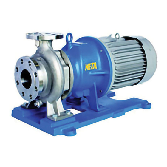
STAINLESS STEEL MAGNET DRIVE PUMP
MTFO/MTFO-L/MTFO-H
INSTRUCTION MANUAL
This instruction manual is for the person who actually operates the pump.
Please be sure this manual is provided to and understood by the operator
on the scene. If the instruction manual is also needed by personnel who
install the pump or by a staff of a plant constructor, please let us know. We
will supply another copy.
Machine Number
To the on-site operator: please enter the pump's code and lot number above and for future parts
order and inquiry.
SANWA HYDROTECH CORPORATION
META SERIES
Requirements
Code
Manual No.MTFO01C(E)/1506ATEX
Original Instruction
Lot Number
Advertisement
Table of Contents

Related Manuals for Sanwa Hydrotech META MTFO

Summary of Contents for Sanwa Hydrotech META MTFO
- Page 1 We will supply another copy. Machine Number Code Lot Number To the on-site operator: please enter the pump’s code and lot number above and for future parts order and inquiry. SANWA HYDROTECH CORPORATION...
- Page 2 Safety Sanwa Hydrotech does not assume responsibility for damage or injury re- sulting from failure to follow the safety instructions contained herein. Be sure therefore to follow the instructions for safe and correct usage when op- erating, performing maintenance, or inspecting the pump.
- Page 3 General Do not use the pump in the presence of explosive gas or powder. You may cause an injury or start a fire. Do not use the pump to pumping a liquid with a low flash point or ignition temperature.
- Page 4 General If using in connection with the food processing, be sure to keep the pump clean by washing. Failure to do so could enable germs to develop in the pump. Do not insert your fingers or any other objects in the openings of the pump motor.
- Page 5 Do not use a damaged motor. Doing so could result in injury or fire. The customer should not modify the pump under any circumstances. Doing so could result in an unexpected accident. Sanwa Hydrotech shall not be responsible for accidents or damage resulting from equipment modified by the customer.
- Page 6 Piping and Wiring Be sure to connect the power cable in accordance with instruction manual for the motor and the connection diagram in the terminal box. Failure to do so could result in electrical shock or fire. Do not forcibly bend, pull or crimp the power cable or motor lead wires. Doing so could result in electrical shock.
- Page 7 General The magnetic pump is designed for liquid only. If the pump is modified or changed without authority and/or other than original spare parts are used for repair works, the explosion protection will be forfeited. Inadmissible mode of operation ...
- Page 8 The situations below will increase the temperature of the pump surface. Do not operate the pump these situations. ・Shut-off operating ・Low-flow operating ・Dry running ・Operating with “decoupling” ・Operating with “circulation-hole of casing cover and shaft is interrupt- ed” Maintenance ...
-
Page 9: Table Of Contents
Contents Introduction for safety ● Instructions for Safe Usage ..........10 Equipment Failure / Accident Prevention and Safe Operation Checks ..............10 Precautions When Pumping Special Liquids ........11 ● Transport and unpacking ..........12 1. Transport ..................12 2. Unpacking ..................12 ●... - Page 10 ● Pump Installation .............. 21 1. Installation ..................21 2. Piping ................... 21 3. Wiring ................... 22 4. Earthing ..................23 5. Cover ................... 23 ● Operation ................24 1. Pre-Operation Inspections (Be sure to turn the power off before performing inspections!) ..........24 2.
-
Page 11: Instructions For Safe Usage
● Instructions for Safe Usage In order to use your Sanwa Magnet Drive Pump in the manner for which it was designed, be sure to read through and get a thorough understanding of the contents of this manual and the installation instructions before at- tempting to install, operate, perform maintenance or inspections. -
Page 12: Precautions When Pumping Special Liquids
Precautions When Pumping Special Liquids Sanwa pumps are used in various industries. Our stainless steel magnet drive pumps in particular are frequently used for pumping hazardous liquids, and fluids which tend to produce food germs. Mishandling in any of these cases could lead to serious consequences such as bodily injury, loss of life or property damage. -
Page 13: Transport And Unpacking
● Transport and unpacking 1. Transport When transporting the pump, be careful not to drop it or let it fall. Take the appropriate method, such as picking up by two people or lifting by belt, to avoid risk. Make sure the eyebolts (if the pump is equipped with them) are used to secure the pump during transportation. -
Page 14: Preliminary Check
● Preliminary Check When your pump is delivered, you should check the following items: Are all of the accessories included in the package? Check the name plate to make sure the merchandise is as ordered. Check to make sure the pump has not been damaged or the bolts and nuts loosened during transport. -
Page 15: Pump Model Identification
● Pump Model Identification MTF O -H 40X25-160 PUMP TYPE PUMP SIZE MAGNET COUPLING TYPE 1. Impeller Type : OPEN IMPELLER 2: Liquid Temperature Selection Guide (BLANK) : STANDARD MODEL -L : LOW TEMPERATURE MODEL -H : HIGH TEMPERATURE MODEL TYPE Min. -
Page 16: Magnet Type
PUMP SUCTION DISCHARGE MOTOR MOTOR SIZE SIZE (mm) SIZE (mm) (kW) FRAME 40x25-160 40x25-200 50x40-160 50x40-200 50x40-250 112M~ 3.7~22 180M/L 80x50-160 80x50-200 80x50-250 100x80-160 100x80-200 4. MAGNET TYPE W : W TYPE COUPLING... -
Page 17: Pump Specification
● Pump Specification 1. DESIGN PRESSURE DESIGN PRESSURE (MPa) at 150℃ 40x25-160 40x25-200 50x40-160 50x40-200 MTFO 50x40-250 MTFO-L 80x50-160 80x50-200 MTFO-H 80x50-250 100x80-160 100x80-200 2. Casing Piping Connection Suction and Discharge:JIS 10K RF Flange (steel pipe flange JIS B 2220) ASME 150lb RF Flange (ASME B16.5) DIN PN16 Flange (Flanges and their joints EN1092-1) Drain:Rc threads (taper pipe threads JIS B 0203/ISO 7-1) -
Page 18: Parts Specifications Of Each Liquid Temperature Range
5. Parts Specifications of Each Liquid Temperature Range RANGE Parts (BLANK) −L −H (−30~+150℃) (−80℃~R.T.) (R.T.~+280℃) CASING STANDARD MODEL EXTREME TEMP. MODEL COVER (with O ring) (without O ring) & REAR CASING SHAFT STANDARD MODEL HIGH TEMP. MODEL STANDARD MODEL HIGH TEMP. -
Page 19: Marking
The maximum surface temperature of the pump is the highest temperature ascertained from any one of the following conditions: 1. the temperature of the liquid plus, 20℃ 2. the temperature of the ambient temperature, plus 20℃ Thus, the maximum liquid temperature for each temperature class is below. Temperature class Maximum temperature of liquid 280℃... -
Page 20: Declaration Conformity
③Dust: D ④Protection measure:c construction safety ⑤Maximum surface Temperature:(see above chapter 9) It depends on the temperature of pump liquid and ambient temperature. Declaration of Conformity... -
Page 22: Pump Installation
● Pump Installation 1. Installation The position of the pump should be finalized after considering the pump suction capacity. If the suction head is not enough, cavitations and ab- normal vibration/noise will occur. The pump should be installed in a place which provides sufficient space for maintenance and inspections. -
Page 23: Wiring
3. Wiring Power supply equipment, wiring and the earth terminal connection should be in accordance with technical standards for electrical equip- ment and inner wiring diagrams. Piping or the earth terminal connecting work performed by unqualified personnel is not only in violation of the law, but is extremely dangerous. -
Page 24: Earthing
4.earthing Pumps that have been supplied in accordance to the ATEX Directive (94/4/EC) will be identified by a label with the following symbol on it; Once pump has been installed, the earth of motor terminal box should be wired to earth with a suitable earthing cable. 5.cover ... -
Page 25: Operation
● Operation 1. Pre-Operation Inspections (Be sure to turn the power off before performing inspections!) 1. Tighten flange bolts and machine base bolts. 2. Supply liquid after thoroughly cleaning the inside of piping and tanks. 3. Check if you can turn the motor by hand without supplying power. 4. -
Page 26: Operation And Handling
Be sure to completely close the gate valve of discharge pipe before starting the pump. 2. When the pump arrives at the specified speed, open the gate valve within one minute. 3. When the pump starts, check for abnormal noises, vibration, or rising discharge pressure. - Page 27 High Temperature If pumping hot liquids, do not place your hands or other parts of your body near the casing or frame adapter. Doing so could result in skin burns. No-Load Operation Prohibited The bearings are lubricated by liquid pumped. Running the pump without liquid to be pumped should be avoided.
- Page 28 If a power unit does not meet the power required, “decoupling” will be occurred and then the temperature of pump surface will rise up. Variation in Performance According to Viscosity Discharge flow rate and the total head of pumps are lower for high viscosity liquids than when using fresh water, and more power is required to pump viscous liquids.
-
Page 29: Shutting Down
Noise Level Typical sound pressure levels measured in dB(A)(at 1m) are shown in the table below. (In case of using typical motor) Pump noise level depends on a number of factors – the type of driver, the operating capacity, piping design and acoustic characteristics of the building. If the motor is driven by inverter, noise level will be increased. -
Page 30: Maintenance And Inspection
● Maintenance and Inspection 1. Routine Inspection Item Advice Does the pump run smoothly Permissible amplitude of vibration for the without vibration? pump with 2P motor is 28/33µm as maximum 47/54µm, maximum pump equipped with 4P motor(60/50Hz). If abnormal noise is produced by the bearings or other parts, stop the pump immediately and check each part. -
Page 31: Configuration And Location Of Part
2. Configuration and Location of Part A list of parts (below) and a configuration diagram (following page) are given to provide a general description of the pump. You may refer to these as you read the instruction manual. Parts Parts Material Qty. -
Page 32: Configuration
Configuration (MTFO) - Page 33 Configuration (MTFO-H)
- Page 34 Configuration (MTFO-L)
-
Page 35: Order Of Disassembly And Assembly
3. Order of Disassembly and Assembly The magnet coupling uses powerful magnets which attract metal and other magnetic materials. The workbench, therefore, should be made of wood or plastic. We recommend the use of non-magnetic stainless steel tools for disas- sembling the pump. - Page 36 (Photo.2) (Photo.1) (Photo.4) (Photo.3) (Photo.6) (Photo.5) (Photo.8) (Photo.7) (Photo.10) (Photo.9)
- Page 37 If pumping hazardous chemicals, be sure to wash the pump thoroughly after draining the liquid. A small amount of liquid will however remain in the screw, faucet joint and engaged parts inside the pump. If handling hazardous chemicals, be sure to wear protective equipment such as glasses and rubber gloves, and proceed with caution while disassem- bling the pump.
-
Page 38: Checking Parts Dimension And Clearance Gap
4.Checking parts dimension and clearance gap If the clearance between rotating and stationary components is out of limitation, it may happen that these component contact and resulting frictional heat entail excessive temperatures. Check the following dimensions, when disassembled. If measured di- mension exceed the allowance, replace damaged parts by new original spare parts. - Page 39 ・Clearance between Impeller and casing X’ X’’ (mm) (mm) (mm) 0.6~1.4 0.7~1.3 At 0 X” means clearance between Bushing(front) and Thrust ring(front). Opened impeller’s clearances (X and X’) has priority over Gap of journal bearing. In case of that opened impeller’s clearance is out of allowance by wear of bearing, replace bushing or thrust ring with new spare parts, even if they are within al- lowance range.
-
Page 40: Optimal Tightening Torque For Bolts And Nuts
5. Optimal Tightening Torque for Bolts and Nuts Part 3A , 62 HEXAGON HEXAGON SLEEVE IMPELLER SOCKET HEXAGON SET SCREW SOCKET BOLT SCREW SCREW HEAD HEAD BOLT HEAD BOLT BOLT M12/M16 M5/M6 M12/M16 29.5/75.5N・m 1.5/2.4N・m 98.1N・m 2.4N・m 6.0N・m 42.2/108N・m 12N・m 42.2N・m (3.0/7.7kgf・m) (0.15/0.24kgf・m) -
Page 41: Troubleshooting
●Troubleshooting The following table contains the causes and countermeasures for typical prob- lems that may occur. You may refer to the table when there seems to be some- thing wrong with your pump. (Items particular to magnet pumps are indicated by a circle (○). - Page 42 Problem Possible Causes Countermeasures ● Head of liquid is too low or too ● Throttle discharge valve. much discharge flow rate. ● Specific gravity or viscosity of ● Reconsider planning. liquid is too high. Overloading ● Irregular contact at rotating part ● Repair or replace part. ○...
-
Page 43: Repairs And Warranty
Sanwa Hydrotech Corp., or contractor appointed by Sanwa Hydrotech Corp., 3. Sanwa Hydrotech Corporation shall not assume responsibility for expenses or damage incurred as a result of failure of this product while being used. - Page 44 MANUFACTURE:SANWA HYDROTECH JAPAN SANWA HYDROTECH CORPORATION OVERSEAS BUSINESS DEPT. No. 11-13, MINAMIKANEDEN 2-CHOME, SUITA, OSAKA 564-0044, JAPAN PHONE:+81-6-6330-5984 FAX: +81-6-6330-5975 E-mail:sxobd@sanwapump.co.jp Web SITE at:www.sanwapump.com LOCAL REPRESENTATIVE: Manufacturer : SANWA HYDROTECH CORPORATION No. MTFO01C(E)/1506ATEX...
Need help?
Do you have a question about the META MTFO and is the answer not in the manual?
Questions and answers