Table of Contents
Advertisement
Quick Links
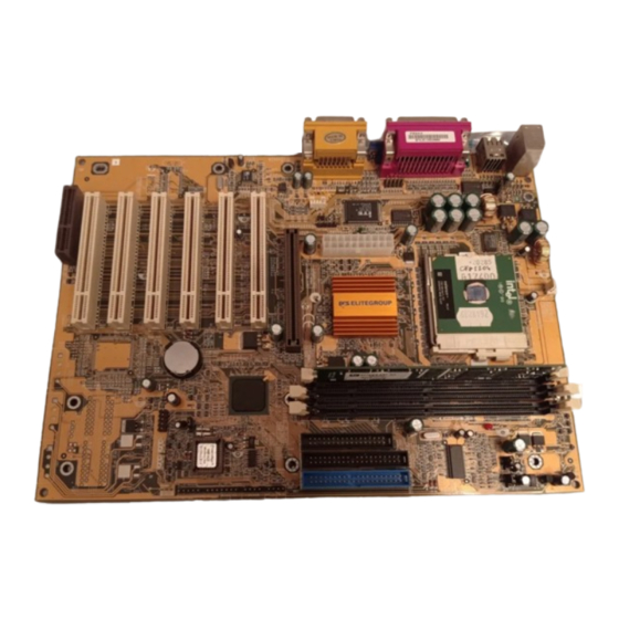
When installing a CPU heatsink and
Caution!
cooling fan make sure that you DO NOT
scratch the motherboard or any of the
surface-mount resistors with the clip of
the cooling fan. If the clip of the cooling
fan scrapes across the mainboard, you
may cause serious damage to both the
mainboard and the processor.
On most mainboards, there are small
surface-mount
processor socket, which may be damaged
if the cooling fan is carelessly installed.
Avoid using cooling fans with sharp
edges on the fan casing and the clips.
Also, install the cooling fan in a well-lit
work area so that you can clearly see the
mainboard and processor socket.
Important Information
Copyright
This publication, including all photographs, illustrations and
software, is protected under international copyright laws, with all
rights reserved. Neither this manual, nor any of the material
contained herein, may be reproduced without the express
written consent of the manufacturer.
Version 1.0
Disclaimer
The information in this document is subject to change without
notice. The manufacturer makes no representations or
warranties with respect to the contents hereof and specifically
disclaims any implied warranties of merchantability or fitness for
any particular purpose. Furthermore, the manufacturer reserves
the right to revise this publication and to make changes from
time to time in the content hereof without obligation of the
manufacturer to notify any person of such revision or changes.
resistors
near
the
CPU socket
i
Cooling fan and
heat sink
Advertisement
Table of Contents

Related Manuals for ECS Electronics P6ISA-II


Summary of Contents for ECS Electronics P6ISA-II
- Page 1 When installing a CPU heatsink and Caution! cooling fan make sure that you DO NOT scratch the motherboard or any of the surface-mount resistors with the clip of the cooling fan. If the clip of the cooling Cooling fan and fan scrapes across the mainboard, you heat sink may cause serious damage to both the...
-
Page 2: Trademark Recognition
Trademark Recognition Microsoft, MS-DOS and Windows are registered trademarks of Microsoft Corp. MMX, Pentium, Pentium-II, Pentium-III, and Celeron are registered trademarks of Intel Corporation. Other product names used in this manual are the properties of their respective owners and are acknowledged. Federal Communications Commission (FCC) This equipment has been tested and found to comply with the limits for a Class B digital device, pursuant to Part 15 of the FCC... -
Page 3: Declaration Of Conformity
Declaration of Conformity This device complies with part 15 of the FCC rules. Operation is subject to the following conditions: This device may not cause harmful interference, and This device must accept any interference received, including interference that may cause undesired operation. -
Page 4: Table Of Contents
Contents Important Information ................i Copyright ...................... i Disclaimer..................... i Trademark Recognition ................ii Federal Communications Commission (FCC)..........ii Declaration of Conformity................iii Canadian Department of Communications..........iii About the Manual ..................iii CHAPTER 1: INTRODUCTION Welcome ....................1 Checklist....................2 Recommendations ................ - Page 5 Installing Other Hardware ..............23 Installing the Processor................23 Installing a Processor.................23 Install the Memory Modules ...............25 Installing a Hard Disk Drive and CD-ROM..........26 Installing a Floppy Diskette Drive..............29 Using the Expansion Slots ................30 Other Options .....................32 Making External Connections ..............34 External Connector Color Coding..............35 CHAPTER 3: SETUP About the Setup Utility.................
- Page 6 HAPTER 4: SOFTWARE About the Software................69 Folders for this Mainboard ..............69 Utility Folder Installation Notes............71 Award Flash Memory Utility ..............71 MediaRing Talk..................71 PC-cillin Software..................72 Super Voice ....................72 Realtek-codec Folder Installation Notes ..........72 Audio Software...................
-
Page 7: Chapter 1: Introduction
Welcome Congratulations on purchasing the KOB 815e FSX mainboard. The mainboard is an ATX mainboard that uses a 4-layer printed circuit mainboard and measures 305 mm x 220 mm. The mainboard has a Socket 370 for FC-PGA Intel Celeron or FC- PGA Pentium III processors that support frontside bus (FSB) speeds up to 133 MHz. -
Page 8: Checklist
This chapter contains the following information: Checklist comprises a list of the standard and optional components that are shipped with this mainboard Recommendations lists some Do’s and Don’ts from the manufacturer to help ensure reliability and performance from this product Features highlights the functions and components that make this one of the best value mainboards on the market... -
Page 9: Recommendations
Recommendations This mainboard automatically determines the CPU clock frequency and frontside bus frequency for the kind of processor that you install. You may be able to change these automatic settings by changing the settings in the system Setup Utility. We strongly recommend that you do not overclock the mainboard to run processors or other components faster than their rated speed. -
Page 10: Features
Features The key features of this mainboard are the wide range of processors that can be installed, and the high level of integration, which includes built-in audio, video, and communications. Processors Functioning as a platform for a value PC, the P6ISM features a Socket 370 accommodating FC-PGA Celeron 533MHz (533A) and higher CPUs that support a 66 MHz FSB as well as FC- PGA Pentium III CPUs that support a 100 or 133 MHz FSB. - Page 11 Inexpensive Memory The mainboard has three DIMM sockets for the installation of 168-pin, 3.3V non-buffered DIMM memory modules. The DIMM memory modules use SDRAM memory chips. The mainboard supports a memory bus of 100 MHz or 133 MHz. Each socket can be installed with from 32 to 512 MB of memory; however, this chipset supports a maximum of 512 MB of memory.
- Page 12 Integrated I/O The mainboard has a full set of I/O ports and connectors. The I/O template on the backplane includes two PS/2 ports for a mouse and keyboard, one serial port, one VGA port, one parallel port, one MIDI/game port, two USB ports and audio jacks for microphone, line-in and line-out.
-
Page 13: Chapter 2: Installation
Quick Installation Table This chapter explains how to successfully install the mainboard into a computer case and build a working system. The installation procedure is as follows: Quick Jumper Provides a quick reference for the jumper Setting settings on this mainboard. Reference Before you Provides advice on choosing a case,... -
Page 14: Quick Jumper Setting Reference
Quick Jumper Setting Reference If you are familiar with most of the material in this chapter, you can prepare the mainboard for installation by using this quick reference to set the jumpers. A detailed description of the jumper settings appears later in this chapter. JP1: Clear BIOS jumper Use this jumper to clear the system BIOS. - Page 15 JP4: CPU frequency select jumper Use this jumper to force a CPU that has a 66 MHz frontside bus (FSB) to run at a 100 MHz FSB speed. Function Jumper Setting Auto Short pins 1-2 Force a 66 MHz FSB to Short pins 2-3 run at 100 MHz FSB Note: The CPU speed is determined by the CPU Host/PCI Clock...
- Page 16 Panel 1: Panel connectors for switches and indicators Use the panel connector to implement the switches and indicators on your system case. Function Pins PANEL1 Power switch 22, 23 Hard disk LED Indicator +20, -21 Power Switch 22-23 Empty pin HDD LED 20-21 Speaker +15, -16, 17, 18...
-
Page 17: Before You Begin
Before You Begin During installation, avoid damaging the mainboard with static electricity. Ensure that you are installing the mainboard into a suitable case. Static Electricity In adverse conditions, static electricity can accumulate and discharge through the integrated circuits and silicon chips on this product. -
Page 18: Choosing A Case
Choosing a Case The mainboard complies with the specifications for the ATX system case. Some features on the mainboard are implemented by cabling connectors on the mainboard to indicators and switches on the system case. Ensure that your case supports all the features required. -
Page 19: How To Set Jumpers
How to Set Jumpers A jumper consists of two or more pins mounted on the mainboard. Some jumpers might be arranged in a series with each pair of pins numbered differently. Jumpers are used to change the electronic circuits on the mainboard. When a jumper cap (or shunt) is placed on two jumper pins, the pins are SHORT. -
Page 20: Preparing The Mainboard
Preparing the Mainboard Mainboard Guide Use the following illustration and key to identify the components on your mainboard. DIMM2 CPUFAN1 DIMM1 DIMM3 CPUFAN1 Socket 370 LED1 LED1 FDD1 COM2 IDE2 IDE1 ATX1 SIR1 AGP1 AGP1 PCI1 PCI1 PANEL1 PCI2 PCI2 PCI3 PCI3 PCI4... - Page 21 Key to Mainboard Components Component Description ATX1 Connector for ATX power supply CPUFAN1 Power connector for CPU cooling fan Keyboard wakeup enable jumper Socket 370 CPU Socket for FC-PGA Pentium III Processor DIMM1/2/3 Three slots for 168-pin SDRAM memory module CPU frequency select jumper (66 ~ 100 MHz) CPU frequency select jumper (100 ~ 133 MHz) LED1...
-
Page 22: I/O Ports Side View
I/O Ports Side View PS/2 Parallel port (LPT1) Game port mouse PS/2 Serial port Microphone keyboard ports COM 1 port Line-in Line-out Key to I/O Ports Component Description PS/2 mouse PS/2 port for pointing device (upper port) PS/2 keyboard PS/2 port for keyboard (lower port) USB ports Two stacked Universal Serial Bus ports LPT1... -
Page 23: Check The Jumper Settings
Check the Jumper Settings Check all the mainboard jumpers to ensure that the mainboard is configured correctly. Note: Pin 1 is indicated by a “1.” CPUFAN1 LED1 AGP1 PCI1 PCI2 PCI3 PCI4 WOL1 WOM1 USB1 PCI5 PCI6 CNR1... - Page 24 JP1: Clear BIOS jumper This jumper lets you erase the BIOS Setup Utility settings that are stored in CMOS memory. You might need to erase this data if incorrect settings are preventing your system from operating. You must first set JP2 to open before you can flash the CMOS. To clear the CMOS memory, turn off the system, disconnect the power cable from the mainboard, and short the appropriate pins for a few seconds.
- Page 25 JP4: CPU frequency select jumper This jumper enables you to force the CPU to clock at a higher frequency than it is rated. Short pins 2 and 3 to force the CPU to run at a 100 MHz FSB instead of a 66 MHz FSB. We recommend that you leave the jumper on the normal operation setting.
-
Page 26: Installing The Mainboard In A Case
Installing the Mainboard in a Case Most system cases have mounting brackets installed in the case, which correspond to the holes in the mainboard. Place the mainboard over the mounting brackets and secure the mainboard into the mounting brackets with screws. Most cases have a choice of I/O templates in the rear panel. -
Page 27: Connecting Internal Components
Connecting Internal Components After you have installed the mainboard into the system case, connect the power cable from the case power supply unit to the mainboard power connector ATX1. Connect the CPU and case fans (if your case has them) to CPUFAN1 or CASFAN1 on the mainboard. - Page 28 Panel Connector The mainboard PANEL connector has a standard set of switch and indicator connectors that are commonly found on system cases. Use the illustration below to make the correct connections to the case switches and indicators. Function Pins PANEL1 Power switch 22, 23 Hard disk LED Indicator...
-
Page 29: Installing Other Hardware
Installing Other Hardware Start installing the essential hardware required to get your system started. Installing the Processor This mainboard has a Socket 370 processor socket. To choose a processor, you need to consider the performance requirements of the system and the price of the processor. Performance is based on the processor design, the clock speed and frontside bus frequency of the processor, and the quantity of internal cache memory and external cache memory. - Page 30 1. Locate the Socket 370 and CPUFAN1. 2. Pull the Socket 370 locking lever away from the socket to unhook it and then raise the locking lever to the upright position. CPU fan connector Socket 370 processor with CPUFAN1 heatsink/cooling fan attached Socket 370 with locking lever in...
-
Page 31: Install The Memory Modules
Install the Memory Modules For this mainboard, you Front Side Bus System Memory Bus (FSB) (SMB) must use 168-pin 3.3V non- Frequency Frequency buffered Dual In-line Memory Modules (DIMMs). 66 MHz 100 MHz The memory chips are 100 MHz 100 MHz standard SDRAM (Synchronous Dynamic 133 MHz... -
Page 32: Installing A Hard Disk Drive And Cd-Rom
3. Push the latches on each side of the DIMM slot down. 4. Install the DIMM module into the slot and press it carefully but firmly down so that it seats correctly. The latches at either side of the slot will be levered upwards and latch on to the edges of the DIMM when it is installed correctly. - Page 33 Installing a Hard Disk Drive 1. Install the hard disk drive into the drive cage in your system case. 2. Plug the IDE cable into the primary IDE channel on the mainboard IDE1. 3. Plug one of the cable IDE connectors into the hard disk drive IDE connector.
- Page 34 Installing a CD-ROM/DVD Drive 1. Install the CD-ROM/DVD drive into the drive cage in your system case. Plug the IDE cable into the primary IDE channel on the mainboard IDE1. 2. Plug one of the connectors on the IDE cable into the IDE connector on the back edge of the CD-ROM/DVD drive.
-
Page 35: Installing A Floppy Diskette Drive
Installing a Floppy Diskette Drive The mainboard has a floppy diskette drive interface and it ships with a diskette drive ribbon cable that supports one or two floppy diskette drives. You can install a 5.25-inch and a 3.5-inch drive with various capacities. -
Page 36: Using The Expansion Slots
Using the Expansion Slots This mainboard has six 32-bit PCI expansion slots, one 4xAGP slot, and a CNR slot. PCI Slots: The PCI slots can be used to install add-in cards that have the 32-bit PCI (Peripheral Components Interconnect) interface. 4xAGP Slot: The 4xAGP can be used to install a graphics adapter that supports the 4xAGP specification and has the 4xAGP edge connector. - Page 37 you may have to manually configure the card before installation. 2. In the system case, remove the blanking plate from the slot in the system case that corresponds to the expansion slot that you are going to use. 3. Position the edge connector of the add-in card over the expansion slot.
-
Page 38: Other Options
Other Options This section lists the other options that come with this mainboard. CPUFAN1 COM2 LED1 AGP1 PCI1 PCI2 SIR1 PCI3 PCI4 WOL1 WOM1 USB1 PCI5 PCI6 CNR1 WOL1 WOM1 USB1 COM2: Extra COM Port Header Connect a serial port extension bracket to this header to add a second serial port to your system. - Page 39 SIR1: Serial Infrared Connector. Connect the cable from the optional IR port to SIR1 (for SIR infrared). After you have connected the cable, secure the optional IR port to the appropriate location on your system case. This option can be purchased from third-party vendors. Note: An IR port may use some of the resources required by a second serial port or a fax/modem card.
-
Page 40: Making External Connections
Making External Connections After you have installed the mainboard, make the connections to the external ports. PS/2 Parallel port (LPT1) Game port mouse PS/2 Serial port Microphone keyboard ports COM 1 port Line-in Line-out 1. There are two stacked PS/2 ports. The upper port can be used by a PS/2 mouse or pointing device. -
Page 41: External Connector Color Coding
External Connector Color Coding To help identify the external connectors, many connectors now use standard colors as shown in the table below. Connector Color Analog VGA Blue Audio line-in Light blue Audio line-out Lime Digital monitor / flat panel White IEEE 1394 Grey Microphone... - Page 42 —Notes—...
-
Page 43: Chapter 3: Setup
About the Setup Utility The computer employs the latest Award BIOS CMOS chip with support for Windows Plug and Play. This CMOS chip contains the ROM setup instructions for configuring the mainboard’s BIOS. The BIOS (Basic Input and Output System) Setup Utility is a ROM-based configuration utility that displays the system’s configuration status and provides you with a tool to set system parameters. - Page 44 A standard configuration has already been set in the Setup Utility. However, we recommend that you read this chapter just in case you need to make any changes in the future. This program should be executed under the following conditions: •...
-
Page 45: Entering The Setup Utility
Entering the Setup Utility When the system is powered on, the BIOS will enter the Power- On Self Test (POST) routines. These routines perform various diagnostic checks; if an error is encountered, the error will be reported in one of two different ways: If the error occurs before the display device is initialized, a series of beeps will be transmitted. -
Page 46: Bios Navigation Keys
BIOS Navigation Keys Listed below are explanations of the keys displayed at the bottom of the screens: Function Escape key: Exits the current menu ← ↓ ↑ → Cursor keys: Scroll through the items on a menu Plus, minus, Page Up and Page Down keys: Modify +/−/PU/PD the selected field’s values F10 key: Saves the current configuration and exits setup... -
Page 47: Using Bios
Using BIOS When you start the Setup Utility, the main menu appears. The main menu of the Setup Utility shows a list of the options that are available. A highlight indicates which option is currently selected. You can use the cursor arrow keys to move the highlight to other options. -
Page 48: How To Flash A New Bios
How to Flash a New BIOS You can install updated BIOS for this mainboard that you can download from the manufacturer’s web site. New BIOS may provide support for new peripherals, improvements in performance or fixes for known bugs. Install new BIOS as follows: 1. -
Page 49: Standard Cmos Features Option
8. In the “File Name to Program” dialog box, type in the filename of the new BIOS and follow the onscreen directions to flash the new BIOS to the mainboard. 9. When the installation is complete, remove the floppy diskette from the diskette drive and restart your computer. If your mainboard has a Flash BIOS jumper, reset the jumper to protect the newly installed BIOS from being overwritten. - Page 50 IDE Devices Default: None Your computer has two IDE channels (Primary and Secondary) and each channel can be installed with one or two devices (Master and Slave). Use these items to configure each device on the IDE channel. Press <Enter> to display the IDE sub-menu: CMOS Setup Utility –...
- Page 51 Note: Before attempting to configure a hard disk drive, make sure you have the configuration information supplied by the manufacturer of your hard drive. Incorrect settings can result in your system not recognizing the installed hard disk. Access Mode This item defines some special ways that can be used to access IDE hard disks such as LBA (Large Block Addressing).
-
Page 52: Advanced Bios Features Setup Option
Advanced BIOS Features Setup Option This option displays a table of items that define advanced information about your system. You can make modifications to most of these items without introducing fatal errors to your system. Note that the page has a scroll-bar to scroll down to more items. - Page 53 External Cache Default: Enabled Most processors that can be installed in this system use external (L2) cache memory to improve performance. The exceptions are older SEPP Celeron CPUs running at 266 or 300 MHz. Enable this item for all but these two processors. CPU L2 Cache ECC Checking Default: Enabled This item enables or disables ECC (Error Correction Code) error...
- Page 54 Boot Up Floppy Seek Default: Enabled If this item is enabled, it checks the geometry of the floppy disk drives at start-up time. You don’t need to enable this item unless you have an old diskette drive with 360K capacity. Boot Up NumLock Status Default: On This item defines if the keyboard Num Lock key is active when your...
- Page 55 HDD S.M.A.R.T. capability: Default: Disabled The S.M.A.R.T. (Self-Monitoring, Analysis, and Reporting Technology) system is a diagnostics technology that monitors and predicts device performance. S.M.A.R.T. software resides on both the disk drive and the host computer. The disk drive software monitors the internal performance of the motors, media, heads, and electronics of the drive.
-
Page 56: Advanced Chipset Features Option
Advanced Chipset Features Option This option displays a table of items that defines critical timing parameters of the mainboard components including the memory, and the system logic. Generally, you should leave the items on this page at their default values unless you are very familiar with the technical specifications of your system hardware. - Page 57 SDRAM RAS-to-CAS Delay Default: 3 This sets the relative delay between the Row Address Strobe (RAS) and the Column Address Strobe (CAS). Options are 2 and 3. SDRAM RAS Precharge Time Default: 3 These four items set the timing and wait states for SDRAM memory. We recommend that you leave these items at the default value.
- Page 58 Use VGA BIOS in VBU Block Default: Enabled For the onboard VGA device, the VGA BIOS is combined with the SYSTEM BIOS. If you want to update the VGA BIOS, you must update the SYSTEM BIOS as well (you cannot update the VGA BIOS only). However, Intel chipsets support the "Video BIOS Update"...
-
Page 59: Integrated Peripherals Option
RAS# Precharge Timing Default: Fast DRAM must continually be refreshed or it will lose its data. Normally, DRAM is refreshed entirely as the result of a single request. This option allows you to determine the number of CPU clocks allocated for the Row Address Strobe (RAS) to accumulate its charge before the DRAM is refreshed. - Page 60 IDE Primary/Secondary Master/Slave UDMA Default: Auto Each IDE channel supports a master device and a slave device. This mainboard supports UltraDMA. UltraDMA technology provides faster access to IDE devices. If you install a device that supports UltraDMA, change the appropriate item on this list to Auto.
- Page 61 Power ON Function Default: Hot KEY KB Power ON Password Default: Enter Hot Key Power ON Default: Ctrl-F12 The Power On Function item allows you to power on the system by pressing hot-keys, or typing a password. If you choose Password, you can use the item KB Power On Password to install a power on password.
- Page 62 Onboard Parallel Port Default: 378/IRQ7 This option is used to assign the I/O address for the onboard parallel port. Parallel Port Mode Default: ECP Enables you to set the data transfer protocol for your parallel port. There are four options: SPP (Standard Parallel Port), EPP (Enhanced Parallel Port), ECP (Extended Capabilities Port) and ECP+EPP.
-
Page 63: Power Management Setup Option
Power Management Setup Option This option displays items that let you control the system power management. Modern operating systems take care of much of the power management. This mainboard supports ACPI (advanced configuration and power interface). The system has various power saving modes including powering down the hard disk, turning off the video, suspending to RAM, and a software power down that allows the system to be automatically resumed by certain events. - Page 64 CMOS Setup Utility – Copyright (C) 1984 – 2000 Award Software Power Management Setup ACPI Function Enabled Item Help ACPI Suspend Type S1(POS) Power Management User Define Menu Level Video Off Method DPMS Video Off In Suspend Suspend Type Stop Grant MODEM Use IRQ Suspend Mode Disabled...
- Page 65 Power Management Default: User Define This item acts like a master switch for the power-saving modes and hard disk timeouts. If this item is set to Max Saving, power-saving modes occur after a short timeout. If this item is set to Min Saving, power-saving modes occur after a longer timeout.
- Page 66 Soft-Off by PWR-BTTN Default: Instant-Off Under ACPI (Advanced Configuration and Power management Interface) you can create a software power down. In a software power down, the system can be resumed by Wake Up Alarms. This item lets you install a software power down that is controlled by the normal power button on your system.
- Page 67 Time (hh:mm:ss) Alarm Default: 0 0 0 When Resume by Alarm is enabled, you can set the time you wish the computer to turn on. **Reload Global Timer Events** Global Timer (power management) events are I/O events whose occurrence can prevent the system from entering a power saving mode or can awaken the system from such a mode.
-
Page 68: Pnp/Pci Configuration Option
PnP/PCI Configuration Option This option displays a table of items that configures how PnP (Plug and Play) and PCI expansion cards operate in your system. CMOS Setup Utility – Copyright (C) 1984 – 2000 Award Software PnP/PCI Configurations Reset Configuration Data Disabled Item Help Resources Controlled by... -
Page 69: Pc Health Status Option
PCI/VGA Palette Snoop Default: Disabled This item is designed to overcome some problems that can be caused by some non-standard VGA cards. This mainboard includes a built-in VGA system that does not require palette snooping so you must leave this item disabled. PC Health Status Option On mainboards that support hardware monitoring, this item lets you monitor the parameters for critical voltages, critical... - Page 70 System Component Characteristics These fields provide you with information about the systems current operating status. You cannot make changes to these fields. The following information is displayed: • Vcore (CPU core voltage) • 1.8 V (2.5 NB core voltage) • 3.3 V Vcc3 (onboard 3.3 volt) •...
-
Page 71: Frequency Control Option
Frequency Control Option This item enables you to set the clock speed and frontside bus frequency for your system. The clock speed and frontside bus are determined by the kind of processor you have installed in your system. CMOS Setup Utility – Copyright (C) 1984 – 2000 Award Software Frequency Control Auto Detect DIMM/PCI Clk Enabled... -
Page 72: Load Fail-Safe Defaults Option
CPU Host/PCI Clock Default: Default CPU Clock Ratio Default: Auto These items appear if you have set the CPU Internal Core Speed to Manual. Use the CPU Host/PCI Clock to set the frontside bus frequency for the installed processor (usually 133 MHz, 100 MHz or 66 MHz). Then use CPU Clock Ratio to set a multiple. -
Page 73: Set Supervisor And User Password Options
Set Supervisor and User Password Options These items can be used to install a password. A Supervisor password takes precedence over a User password, and the Supervisor can limit the activities of a User. To install a password, follow these steps: 1. -
Page 74: Save & Exit Setup Option
Save & Exit Setup Option Highlight this item and press <Enter> to save the changes that you have made in the Setup Utility and exit the Setup Utility. When the Save and Exit dialog box appears, press <Y> to save and exit, or press <N>... -
Page 75: Hapter 4: Software
About the Software The software for this mainboard is supplied on a CD-ROM. The disk has some folders that can be used by many different mainboards, for example the UTILITY and PERIPHERAL folders. Some folders can only be used by mainboards which have certain brands of chipsets, for example the INTEL and VIA folders. - Page 76 Realtek-codec Folder You can use the software from the REALTEK-CODEC\INTEL folder: Windows 2000: Windows 2000/NT drivers and software for the built-in audio system Windows 98: Windows 98 drivers and software for the built-in audio system Intel Folder 81XVGA: This folder has Intel 815 chipset graphics drivers for Windows 2000/98/95/NT.
-
Page 77: Utility Folder Installation Notes
Utility Folder Installation Notes Award Flash Memory Utility This utility lets you erase the system BIOS stored on a Flash Memory chip on the mainboard, and lets you copy an updated BIOS to the chip. Take care how you use this program. If you erase the current BIOS and fail to write a new BIOS, or write a new BIOS that is incorrect, your system will malfunction. -
Page 78: Pc-Cillin Software
PC-cillin Software The PC-cillin software program provides anti-virus protection for your system. This program is available for: DOS – \UTILITY\PC-CILLIN\DOS\PCSCAN.EXE Win98 – \UTILITY\PC-CILLIN\WIN98\SETUP.EXE Anti-virus software is provided for DOS and WIN 98. Browse to the appropriate directory for your operating system. For DOS, copy all the files in the DOS folder to your hard disk drive and run PSCAN to scan your system. -
Page 79: Intel Folder Installation Notes
Windows 98 Installation To install the audio applications in Windows 98, browse to the \REALTEK-CODEC\INTEL\WIN98 folder; then run the SETUP.EXE program. Intel Folder Installation Notes 81XVGA This folder has the software and drivers for the graphics system built into the 815 chipset. Select the folder for the operating system that you are running, browse to the subfolder \GRAPHICS\ and then begin the installation by running SETUP.EXE. - Page 80 —Notes—...
-
Page 81: Appendix: Jumper Setting Reference
Jumper Setting Quick Reference JP1: Clear BIOS jumper Use this jumper to clear the system BIOS. Function Jumper Setting Normal operation Short pins 1-2 Clear CMOS Short pins 2-3 JP2: BIOS flash protect jumper Use this 2-pin jumper to protect the system BIOS from being accidentally flashed (updated). - Page 82 Note: The CPU speed is determined by the CPU Host/PCI Clock speed multiplied by the CPU Clock Ratio. Refer to the Frequency Control Option in Chapter 3 for more information. Forcing the CPU to run at a higher clock speed then it was rated for is called overclocking and is not recommended.
- Page 83 FP1: Panel connectors for switches and indicators Use the panel connector to implement the switches and indicators on your system case. Function Pins PANEL1 Power switch 22, 23 Hard disk LED Indicator +20, -21 Power Switch 22-23 Empty pin HDD LED 20-21 Speaker +15, -16, 17, 18 Empty pin...
Need help?
Do you have a question about the P6ISA-II and is the answer not in the manual?
Questions and answers