Table of Contents
Advertisement
Quick Links
Trademarks
ANCEL is trademark of OBDSPACE TECHNOLOGY CO., LTD
All other marks are trademarks or registered trademarks of their respective holders.
Copyright Information
©OBDSPACE TECHNOLOGY CO., LTD
All rights reserved.
Disclaimer
The information, specifications and illustrations in this manual are based on the latest information
available at the time of printing.
ANCEL reserves the right to make changes at any time without notice.
Visit our website at:
www.anceldirect.com
For Technical Assistance, send us email at
support@anceldirect.com
1
AD610 Elite ABS & Airbag Reset Tool Manual_English_V1.01
Advertisement
Table of Contents

Summary of Contents for OBDSPACE TECHNOLOGY ANCEL AD610
- Page 1 Trademarks ANCEL is trademark of OBDSPACE TECHNOLOGY CO., LTD All other marks are trademarks or registered trademarks of their respective holders. Copyright Information ©OBDSPACE TECHNOLOGY CO., LTD All rights reserved. Disclaimer The information, specifications and illustrations in this manual are based on the latest information available at the time of printing.
-
Page 2: One-Year Limited Warranty
One-Year Limited Warranty Subject to the conditions of this limited warranty, ANCEL warrants its customer that this product is free of defects in material and workmanship at the time of its original purchase for a subsequent period of one (1) year. In the event this product fails to operate under normal use, during the warranty period, due to defects in materials and workmanship, ANCEL will, at its sole option, either repair or replace the product in accordance with the terms and conditions stipulated herein. - Page 3 TO LOSS OF ANTICIPATED BENEFITS OR PROFITS, LOSS OF SAVINGS OR REVENUE, LOSS OF DATA, PUNITIVE DAMAGES, LOSS OF USE OF THE PRODUCT OR ANY ASSOCIATED EQUIPMENT, COST OF CAPITAL, COST OF ANY SUBSTITUTE EQUIPMENT OR FACILITIES, DOWNTIME, THE CLAIMS OF ANY THIRD PARTIES, INCLUDING CUSTOMERS, AND INJURY TO PROPERTY, RESULTING FROM THE PURCHASE OR USE OF THE PRODUCT OR ARISING FROM BREACH OF THE WARRANTY, BREACH OF CONTRACT, NEGLIGENCE, STRICT TORT, OR ANY OTHER LEGAL OR EQUITABLE...
-
Page 4: Safety Information
Safety Information For your own safety and the safety of others, and to prevent damage to the equipment and vehicles, read this manual thoroughly before operating your scanner. The safety messages presented below and throughout this user’s manual are reminders to the operator to exercise extreme care when using this device. -
Page 5: Table Of Contents
Table of Contents ONE-YEAR LIMITED WARRANTY........................2 SAFETY INFORMATION............................4 ......................4 AFETY ESSAGE ONVENTIONS ........................4 MPORTANT AFETY NSTRUCTIONS 1 USING THIS MANUAL............................7 1.1 B ..............................7 1.2 S ............................7 YMBOLS AND CONS 1.2.1 Solid Spot............................7 1.2.2 Arrow Icon............................7 1.2.3 Note and Important Message...................... - Page 6 5 OBDII/EOBD OPERATIONS..........................28 5.1 S ............................28 YSTEM TATUS 5.2 R .............................. 29 ODES 5.3 E ............................31 RASE ODES 5.4 L ..............................31 5.4.1 Complete Data List.......................... 32 5.4.2 Custom Data List..........................34 5.5 F ............................35 REEZE RAME 5.6 R I/M R ......................
-
Page 7: Using This Manual
1 Using This Manual We provide tool usage instructions in this manual. Below is the conventions we used in the manual. 1.1 Bold Text Bold text is used to highlight selectable items such as buttons and menu options. Example: Press the ENTER button to select. 1.2 Symbols and Icons 1.2.1 Solid Spot Operation tips and lists that apply to specific tool are introduced by a solid spot ●. -
Page 8: Introduction
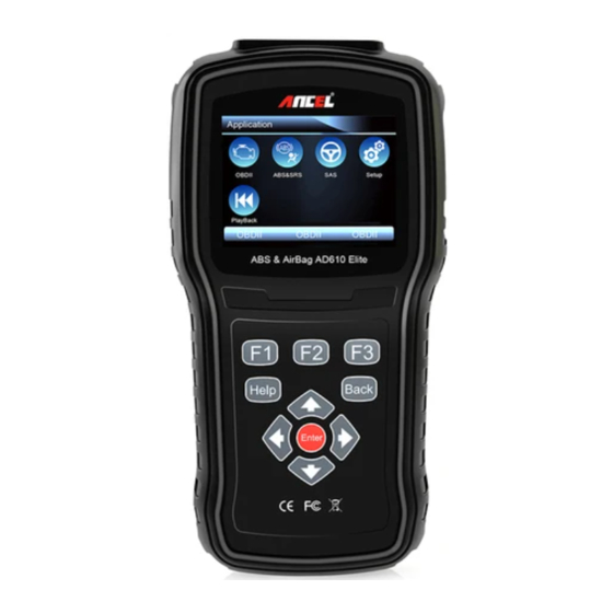
2 Introduction AD610 professional ABS & Airbag Reset Tool works on most vehicles on the road today. It does not only have extensive coverage of vehicles but also provides accurate and professional diagnosis of ABS and airbag faults. With the tool properly connected to the vehicle’s data link connector (DLC), you can use the scanner to read diagnostic trouble codes and view “live”... -
Page 9: Accessory Descriptions
IMPORTANT Do not use solvents such as alcohol to clean keypad or display. Use a mild nonabrasive detergent and a soft cotton cloth. 2.2 Accessory Descriptions This section lists the accessories that go with the scanner. If you find any of the following items missing from your package, contact your local dealer for assistance. -
Page 10: Connecting To Vehicle Power
1. Locate the data link connector (DLC). The DLC is generally located under the dash on the driver side of the vehicle. 2. Attached the diagnostic cable to the scanner and tighten the captive screws to ensure good connection. 3. Connect a correct adapter to the data cable according to the vehicle being serviced and plug it into the vehicle DLC. -
Page 11: Input Dialog Box
3.3 Input Dialog Box This section illustrates how to use the scan tool to input letters and numbers, such as VIN number, channel number, test values and DTC number. Typically, you may be required to input letters or numbers when you are doing any of the following operations. VIN entry ●... -
Page 12: Diagnostic Operations
3. To delete a letter or number, use the function key Previous to move the cursor to it and then press the Backspace button. 4. When finished the entry, press Finish key to continue. 4 Diagnostic Operations This section illustrates how to use the scanner to read and clear diagnostic trouble codes, and view “live”... - Page 13 2. A screen with vehicle manufacturer areas displays. Select the area where the vehicle manufacturer is from. A menu of all vehicle manufacturers from this area displays. Figure 4-2 Sample Vehicle Manufacturer Area Selection Screen 3. Select the vehicle manufacturer. A list of vehicle identification options displays. Figure 4-3 Sample Vehicle Manufacturer Selection Screen 4.
-
Page 14: Manual Vin Entry
Figure 4-5 Sample VIN Automatic Acquisition 6. Answer YES if the Vehicle Specification or VIN code is correct and a menu of controller selection displays. Answer NO if it is incorrect, and you are required to enter the correct VIN number manually. -
Page 15: Manual Vehicle Selection
Figure 4-7 Sample Manual VIN Entry with Keyboard 3. Input a valid VIN code and use the function key Finish to confirm. The scan tool starts to identify the vehicle. 4.1.3 Manual Vehicle Selection Manual Vehicle Selection identifies a vehicle by making several selections according to certain VIN characters, such as model year, and engine type. - Page 16 Figure 4-9 Sample System Menu Screen 2. When the test finished, press the function key Save on the screen, and a screen with a QWERTY keyboard displays. Figure 4-10 Sample Save Vehicle Record Screen 3. Enter a unique name for this vehicle and save it, and you will see this new vehicle in Vehicle Data Recorder menu.
-
Page 17: System Selection
Figure 4-12 Sample tested vehicle identification screen 2. Select the vehicle under test and press the ENTER key. 4.2 System Selection When you have completed the identification of vehicle, a menu for selecting system to test displays. Menu options typically include: Auto Scan ●... - Page 18 Figure 4-15 Sample auto scan screen 4. If there is diagnostic trouble code(s) detected in a control unit, press the function key corresponding with Display DTC on the screen to view details of code information, and press the function key Quick Erase to clear them. Figure 4-16 Sample Display DTC screen 5.
-
Page 19: Control Unit
4.2.2 Control Unit Control Unit screen displays all controllers available of the vehicle manufacturer. The controllers listed on the menu do not mean that they are installed on the vehicle. To select a system for testing: 1. Scroll with the arrow keys to highlight Control Unit from the menu and press the ENTER key. A controller menu displays. -
Page 20: Read Codes
Not all function options listed above are applicable to all vehicles. Available options may vary by the year, model, and make of the test vehicle. A “The selected mode is not supported!” message displays if the option is not applicable to the vehicle under test. 4.3.1 Read Codes Read Codes menu lets you read trouble codes found in the control unit. -
Page 21: Erase Codes
4.3.2 Erase Codes Erase Codes menu lets you to clear all current and stored DTCs from a selected control module. Also it erases all temporary ECU information, including freeze frame. So make sure that the selected system are completely checked and serviced by technicians and no vital information will be lost before clearing codes. -
Page 22: Live Data
Figure 4-24 Sample Function Menu Screen 2. A screen with detailed information of the selected control module displays. Figure 4-25 Sample ECU Information Screen 3. Press function key Save to store ECU information. Or use the BACK key to exit. 4.3.4 Live Data Live Data menu lets you view and record real time PID data from a selected vehicle electronic control module. - Page 23 Figure 4-26 Sample Live Data Selection Screen 2. Select the Complete List from the menu and press the ENTER key to display the datastream screen. Figure 4-27 Sample Complete List Screen 3. Scroll with the up and down arrow keys to highlight a line, if the One Graphic on the bottom is highlighted, it indicates the graphing is available for the selected line.
-
Page 24: Custom Data List
Figure 4-29 Sample Two PID Graph Screen 5. Press the function key Merge Graph to display two PID plots in one coordinate for easy and intuitive diagnosis. Figure 4-30 Sample Merged PID Plots Screen 6. To record the data to memory of the scanner, use the function key SAVE, and press Stop Saving to stop recording at any time. - Page 25 Figure 4-31 Sample Live Data Screen 2. The custom datastream selection screen displays. Scroll with the up and down arrow keys to highlight a line, press the ENTER key and then repeat the action to make more selections. Figure 4-32 Sample Custom List Selection Screen NOTE To deselect an item, select it again and then press the ENTER key.
-
Page 26: Special Functions
4.3.5 Special Functions Special tests are bi-directional diagnostic tests on anti-lock brake systems and air bags. The tests let you to use the scanner temporarily activate or control a vehicle system or component, and when you exit the test, the system/component returns to normal operation. Some tests display a command to the operator. - Page 27 System Identification – displays information about the brake system, the vehicle, and the ● ABS controller. TCS Test – allows to control the pump motor in order to apply fluid pressure to the front wheel ● circuits. Traction Control System (TCS) Manual Control Tests – allows to perform motor tests and ●...
-
Page 28: Obdii/Eobd Operations
5 OBDII/EOBD Operations OBD-II/EOBD menu lets you access all OBD service modes. According to ISO 9141-2, ISO 14230-4, and SAE J1850 standards, the OBD application is divided into several sub programs, called ‘Service $xx’. Below is a list of OBD diagnostic services: Service $01 - request current powertrain diagnostic data ●... -
Page 29: Read Codes
Figure 5-1 Sample Diagnostic Menu Screen 2. A screen with detailed information displays. Figure 5-2 Sample System Status Screen 5.2 Read Codes Read Codes menu lets you read both stored codes and pending codes found in the control unit. Typical menu options include: Stored Codes ●... - Page 30 Figure 5-4 Sample Read Codes Screen If no DTCs are present the message “No (Pending) Codes Found!” is displayed. If any manufacturer specific or enhanced codes detected, select vehicle a make before viewing DTC information. Figure 5-5 Sample No Codes Screen 3.
-
Page 31: Erase Codes
5.3 Erase Codes Erase Codes menu lets you to clear all current and stored DTCs from the control module. Also it erases all temporary ECU information, including freeze frame. So make sure that the selected system are completely checked and serviced by technicians and no vital information will be lost before clearing codes. -
Page 32: Complete Data List
Custom Data List ● 5.4.1 Complete Data List Complete Data List menu lets you view all live PID data from a selected system. To view all live PID data: 1. Scroll with the arrow keys to highlight Live Data from Diagnostic Menu and press the ENTER key. - Page 33 Figure 5-11 Sample Complete List Screen 4. Scroll with the up and down arrow keys to highlight a line, if the One Graphic on the bottom is highlighted, it indicates the graphing is available for the selected line. Press the function key One Graphic to display the PID graph.
-
Page 34: Custom Data List
7. To record the data to memory of the scanner, use the function key SAVE, and press Stop Saving to stop recording at any time. 8. Select Text to return to text viewing of PID data. 9. Press Pause to suspend collecting data and use the Start key to resume collecting data. Use the Back key to return to diagnostic menu. -
Page 35: Freeze Frame
Figure 5-17 Sample Datastream Screen 5.5 Freeze Frame Freeze Frame menu displays freeze frame data, a snapshot of critical vehicle operating conditions automatically recorded by the on-board computer at the time of the DTC set. It is a good function to help determine what caused the fault. To view freeze frame data: 1. -
Page 36: Read I/M Readiness Status Data
Figure 5-19 Sample Freeze Data Screen 3. Press function key Save to store freeze frame information. Or use the BACK key to exit. 5.6 Read I/M Readiness Status Data I/M Readiness option allows to view a snapshot of the operations for the emission system on OBDII/EOBD vehicles. - Page 37 Figure 5-20 Sample Diagnostic Menu Screen 2. Depending on readiness test, one of these 2 screens will be present. Use the up and down arrow keys to scroll through data to select lines, and left and right arrow keys to scroll back and forth through different screens of data.
-
Page 38: O2 Monitor Test
5.7 O2 Monitor Test OBD II regulations require certain vehicles monitor and test oxygen (O2) sensors to isolate fuel and emissions related faults. The O2 Monitor Test function is used to retrieve completed O2 sensors monitor test results. The O2 Monitor Test is not an on-demand test. O2 sensors are not tested when selected via the menu but tested when engine operating conditions are within specified limits. -
Page 39: On-Board Monitor Test
Figure 5-25 Sample O2 Bank1 Sensor 1 Screen 4. Press Enter key to view data of selection. Figure 5-26 Sample data of $81 screen 5. Press the BACK key to exit and return. 5.8 On-Board Monitor Test The On-Board Monitor Test function is useful after servicing or after clearing a vehicle ECU’s memory. - Page 40 Figure 5-27 Sample Diagnostic Menu Screen 2. Depending on the protocol the vehicle used, one of these 2 screens shows. Figure 5-28 Sample Non-CAN Vehicle Test Screen Figure 5-29 Sample CAN vehicle test screen 3. Scroll with the arrow keys to highlight a test group and press the ENTER key to confirm. A screen with details of the selected sensor displays.
-
Page 41: Component Test
Figure 5-30 Sample Non-CAN vehicle test screen For CAN vehicles, test screen is illustrated as below: Figure 5-31 Sample Can vehicle test screen 4. Press the BACK key to exit and return. 5.9 Component Test Component Test allows the scanner to control operation of vehicle components, tests or systems. NOTE Some manufacturers do not allow tools to control vehicle systems. -
Page 42: Request Vehicle Information
Figure 5-32 Sample Diagnostic Menu Screen 2. Scroll with the arrow keys to highlight a system or component, press the ENTER key to start test and the scanner displays the message “Command Sent!”. Figure 5-33 Sample Component test screen 3. Press the BACK key to exit and return. 5.10 Request Vehicle Information Vehicle Information allows to request the vehicle’s VIN number, calibration ID(s) which identifies software version in vehicle control module(s), calibration verification numbers (CVN(s)) and... - Page 43 Figure 5-34 Sample Diagnostic Menu Screen 2. Follow on-screen instruction and send the command to read vehicle information. A screen with a list of available options displays. Figure 5-35 Sample Vehicle Info Screen 3. Scroll with the arrow keys to highlight an available option and press the ENTER key. A screen with details of the selected option displays.
-
Page 44: Modules Present
5.11 Modules Present The scanner identifies module IDs and communication protocols for OBD2 modules in the vehicle. To view module IDs and communication types: 1. Scroll with the arrow keys to highlight Modules Present from Diagnostic Menu and press the ENTER key. - Page 45 Figure 5-39 Sample Diagnostic Menu Screen 2. Enter a valid code number and press the function key Finish. Figure 5-40 Sample DTC Lookup Screen 3. A screen with code number and its definition displays. If definition could not be found (SAE or Manufacturer Specific), the scanner displays “DTC definition not found! Please refer to vehicle service manual!”...
-
Page 46: Playback Data
6 Playback Data The PlayBack option leads to screens for review of recorded test results. To review recorded data: 1. Scroll with the arrow keys to highlight PlayBack from home screen and press the ENTER key. Figure 6-1 Sample Home Screen 2. -
Page 47: System Setup
4. If you are reviewing live data or freeze frame data, use the function key Next Frame or Pre. Frame to scroll through all possible frames when necessary. Figure 6-4 Sample Test Data Details Screen 5. To erase a record, scroll with the arrow keys to highlight it and press the function key Delete. To delete all records, press the function key Delete All. -
Page 48: Change Units
Figure 7-1 Sample Setup Screen 2. Press the LEFT/RIGHT arrow key select a language and press the ENTER key to confirm. Press the Back key to exit and return. Figure 7-2 Sample Language Selection Screen 7.2 Change Units Selecting Unit opens a dialog box that allows you to choose between US customary or metric units of measure. -
Page 49: Configure Beeper
Figure 7-4 Sample Language Selection Screen 7.3 Configure Beeper Selecting Beep Set opens a dialog box that allows you to turn on/off the beeper. To turn on/off the beeper: 1. Scroll with the arrow keys to highlight Beep Set from Setup menu and press the ENTER key. Figure 7-5 Sample Setup Screen 2. -
Page 50: Test Keypad
7.4Test Keypad Selecting Key Test option opens a screen that allows you to check the functionality of the keypad. To test the keypad: 1. Scroll with the arrow keys to highlight Key Test from Setup menu and press the ENTER key. Figure7-7 Sample Setup Screen 2. -
Page 51: Tool Information
Figure 7-9 Sample LCD Test Screen 2. To quit the test, press the Back key. 7.6 Tool Information Selecting About option opens a screen that show information about your scan tool, such as serial number and register password which may be required for product registration. To view information of your scan tool: 1. -
Page 52: Configure Shortcut Keys
Figure 7-11 Sample Tool Information Screen 3. Press the Back key to exit and return to the Setup menu. 7.7 Configure Shortcut Keys Selecting Shortcuts option lets you to change the functionality of the shortcut buttons. To assign a function to a shortcut button: 1. -
Page 53: Register The Scanner
8.1 Register the Scanner If you are new to ANCEL, please register the scanner first. All of your scanners can be registered on one ANCEL ID. To register the scanner: 1. Visit our site www.anceldirect.com and then select Register to create an ANCEL ID and register your scan tool. - Page 54 7.Click the check box(es) in front of the software(s) you wish to update and then click the Update button to download and update. When download completed, the downloaded programs start to update automatically. 8.An Update Complete message displays once the updates completed. NOTE If “Update Failed”...
Need help?
Do you have a question about the ANCEL AD610 and is the answer not in the manual?
Questions and answers