Table of Contents
Advertisement
Quick Links
Advertisement
Table of Contents

Summary of Contents for Granite River Labs GRL-USB-PD-A1
- Page 1 User Manual for GRL USB Type C Power Delivery Performance Analyzer (GRL-USB-PD-A1) This material is provided as a reference to install Rev 1.07.03 of Granite River Labs (GRL) USB-PD Type-C™ Power Delivery Performance Analyzer A1 Software. For software support, contact support@graniteriverlabs.com.
-
Page 2: Table Of Contents
3.3 GRL-USB-PD-A1 Analyzer Dimensions and Weight ............... 7 3.4 GRL-USB-PD-A1 Analyzer Electrical specifications ................ 7 3.5 GRL-USB-PD-A1 Analyzer Environment specification ..............7 3.6 GRL-USB-PD-A1 Analyzer Protocol Analysis Host PC Operating Environment ......7 4 Set Contents ............................8 4.1 Hardware components ......................... 8 4.2 Software Components ........................ - Page 3 8 Operation method ..........................14 8.1 Connection diagram ........................14 8.2 Start GRL-USB-PD-A1 Application ....................14 8.3 Capture Start Operation......................14 8.4 Capture Stop operation ......................15 8.5 Clear Capture Data ........................15 8.6 Analysis of Capture Data ......................15 9 Feature Description ...........................
-
Page 4: Overview
1 Overview GRL-USB-PD-A1 can be used to analyze behavior between any USB Type-C based device like Apple Mac’s, Chromebooks and Android phones, Thunderbolt 3 docks, DisplayPort adapters, Qualcomm Quick Charge AC adapters, USB PD power banks, Cable E-Markers, etc. Using passive adapters, the GRL-USB-PD-A1 can also check for power and USB Power Delivery protocol communication over Apple Lightning connectors, and analyze charging behavior over USB micro-B and Type-A connectors. -
Page 5: Power Delivery Message Decode
1.1.2 Power Delivery Message Decode The contents of the captured PD messages are displayed in detail in accordance with the USB PD Specification. -
Page 6: Connection Image
1.2 Connection image 1.3 Power Delivery Protocol Analysis View The image below shows the detailed view of PD Message decode and corresponding CC-Line, VBus and Current measurement. 2 Revision Record Version Revision Description of Changes Author(s) Date 1.0.0 1/12/2017 Added Sections 1 to 6 sky@graniteriverlabs.com 1.0.5 27/9/2018... -
Page 7: Specification
· Operating humidity range: 35 to 85% RH (with no condensation) · Restriction on the use of hazardous substances: REACH, RoHS 3.6 GRL-USB-PD-A1 Analyzer Protocol Analysis Host PC Operating Environment Supported PC: Windows® PC with USB host Supported OS: Windows® 7/8 / 8.1 / 10 (32 bit / 64 bit) -
Page 8: Set Contents
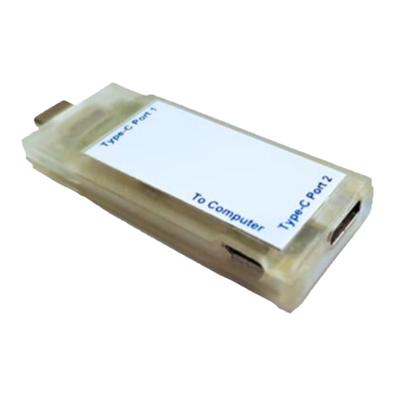
To connect a USB Type-C ™ device that performs PD protocol analysis. 5.2 USB Type-C ™ Receptacle connector To connect a USB Type-C ™ device that performs PD protocol analysis. 5.3 USB Micro-B connector To connect the control PC for GRL-USB-PD-A1 Analyzer viewer. -
Page 9: Status Indicator Led
Ensure to have sufficient space on the hard disk. 6.1 Connection of GRL-USB-PD-A1 Analyzer to Control PC Please connect the micro-B USB port of GRL-USB-PD-A1 Analyzer to the USB port of Control PC with USB cable. 6.1.1 Connection diagram for the software installation 6.2 GRL-USB-PD-A1 Analyzer Driver Installation... - Page 10 Select the GRL-USB-PD-A1 application from the windows menu as shown below. Automatic installation of GRL-USB-PD-A1 driver will start. If the driver is successfully installed, "Media Logic Watt Miru C Device" will be displayed in "Universal Serial Bus Devices" of Device Manager.Device manager screen at driver installation successfully.
-
Page 11: Grl-Usb-Pd-A1 Protocol Analyzer Application Usage
/ current information of VBUS / CC1 / CC2 is displayed as shown below. If GRL-USB-PD-A1 software is not recognized correctly, "Start button" will be disabled and voltage / current information of VBUS / CC1 / CC2 will not be displayed as shown below. -
Page 12: Vbus Current Direction Setting
7.4 VBUS Current Direction Setting In the USB Type-C ™ Power Delivery environment, the supply direction (Sink / Source) of VBUS between Type-C device devices varies depending on the type of connected device and the situation. In this product, the supply direction of VBUS is expressed using "positive / negative of VBUS current value". -
Page 13: Capture File Setting Details
When a capture file with the same file name already exists at the start of capture, it is forcibly saved with the new capture file and the old capture file is deleted. If you want to keep the old capture file, either change the capture file name or check the "Append Timestamp to Filename" checkbox and add the capture start time to the file name so that it will be a different file name and the maximum file size of the capture file is 100 MB. -
Page 14: Operation Method
Note: Capture file save settings is can be changed from the menu or toolbar. 8 Operation method Follow the image below to connect the GRL-USB-PD-A1 Analyzer between the two Type C Devices. Connect micro USB Port of the A1 Analyzer to the Control PC. 8.1 Connection diagram During Protocol Analysis, ensure to keep the GRL-USB-PD-A1 Analyzer always connected to the control PC with the USB cable. -
Page 15: Capture Stop Operation
When the capture is started, the voltage / current information of the captured VBUS / CC1 / CC2 is displayed in real time on the graph. Also, if a PD message is detected, the PD message detected is displayed in the PD message list. 8.4 Capture Stop operation Please press "stop button"... -
Page 16: Operation Screen
9.2 Operation screen The operation screen of the protocol analysis application is as follows. Correlation between the PD Messages, Voltage and Current measurements can be verified. -
Page 17: Description Of Various Tool Bars
Performs a variety of operations, such as saving captured data and read. 9.3 Description of Various Tool bars The GRL-USB-PD-A1 application as various tool bar operations as shown below. Various operations can also be controlled from buttons on the tool bar. -
Page 18: Pd Message List
9.5 PD Message List The below image shows the list of PD messages captured. The below image shows the detailed view of selected PD Message’s selected PD Object: Name Description PD Message List View List of PD Messages captured during analysis PD Packet Description PD Message Header value with PD object list values of the selected PD Message in PD Message List View. -
Page 19: Pd Message Find Operation
9.6 PD Message Find Operation From the PD message list, you can search for a particular PD message. Select Find Option from PD Message Menu as shown above. The Find PD Messages dialog will be displayed. We can specify the search criteria for the PD messages. If the matched PD messages to the search condition are found they would be highlighted in green in the PD Message List View. -
Page 20: Pd Message- Display Filter Setting
During Capture, PD message will be automatically added to the PD message list. The current display position of the list can be automatically moved with respect to the position of the newly added PD message. 5.5 PD Message- 9.8 PD Message- Display Filter Setting In the PD message list, it is possible to display only the specific PD messages. -
Page 21: Pd Message-Font Setting
9.9 PD Message-Font Setting Select PD Message-> Font Settings to change the font of the PD Messages displayed. 9.10 File Export Operation From File Menu Select Export Option to export the captured data to .csv or .wmc format. The Export Dialog would be displayed. - Page 22 From the Export Dialog we can choose to export the selected data to the specified file format. We have option to export the PD Messages along with the Voltage and the Current values in the .csv format. The Export file path would be displayed in the Export Dialog. By clicking the Export button the exported file would be saved in the destination folder.
-
Page 23: Pd Message Time Stamp Feature
9.11 PD Message Time Stamp Feature During Data capture the Timestamp information would be updated in the PD Message List. By default, the time stamp would be showing the Current Position value. For particular PD message the start time is configurable. The Timestamp can be set to Absolute Value. Right click on the PD Message List and select “Set Time Stamp Origin ->Absolute".
Need help?
Do you have a question about the GRL-USB-PD-A1 and is the answer not in the manual?
Questions and answers