Table of Contents
Advertisement
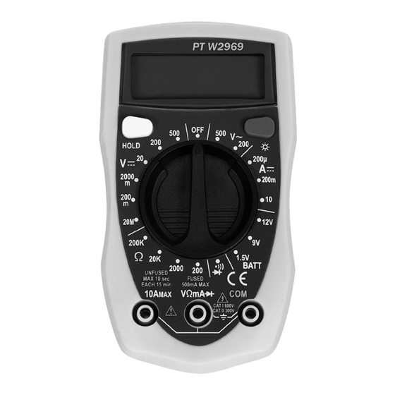
DIGITAL
AUTOMOTIVE MULTIMETER
Item Number W2969
Index
Safety Precautions .................................. 2
Vehicle Service Information .................... 3
Visual Inspection ..................................... 3
Functions and Display Definitions ...... 4
Safety Information ............................... 6
Manual Conventions ............................ 6
International Electrical Symbols ......... 6
Before Using the Multimeter ............... 6
Specifications ..................................... 7
..................................... 7
Setting the Range ............................... 8
Battery and Fuse Replacement ......... 9
Measuring DC Voltage ...................... 10
Measuring AC Voltage ...................... 11
Measuring Resistance ...................... 11
Measuring DC Current .....................
Testing Diodes .................................. 13
Testing Batteries ............................... 14
General Testing ................................. 15
-Testing Fuses ................................. 15
- Testing Switches ............................. 15
- Testing Solenoids and Relays ........
- No Load Battery Test ......................17
- Cranking
- Voltage Drops ................................. 20
- Charging System Voltage Test ...... 21
WARNING: READ, UNDERSTAND AND FOLLOW ALL INSTRUCTIONS AND
�
WARNINGS BEFORE OPERATING THIS TOOL. FAILURE TO DO SO MAY
RESULT IN PERSONAL INJURY AND/OR PROPERTY DAMAGE AND WILL
VOID WARRANTY.
OWNER'S MANUAL
12
16
17
Load Test . 19
- Ignition Coil Testing ........................ 23
- Ignition System Wires ..................... 25
- Reluctance Sensors ........................ 26
- Ox ygen (0
2
- Temperature Type Sensors ............ 31
- Position Type Sensors .................... 32
Electrical Specifications ........................ 34
Warranty .................................................34
25
Advertisement
Table of Contents

Related Manuals for Performance Tool W2969

Summary of Contents for Performance Tool W2969
-
Page 1: Table Of Contents
DIGITAL AUTOMOTIVE MULTIMETER Item Number W2969 OWNER'S MANUAL Index Safety Precautions ........2 Vehicle Service Information ....3 Visual Inspection ........3 1. Multimeter Basic Functions Functions and Display Definitions ..4 Safety Information ....... 6 Manual Conventions ......6 International Electrical Symbols .. -
Page 2: Safety Precautions
Bosch Bosch... -
Page 3: Vehicle Service Information
Vehicle Service Manual – Sources For Service Information The following is a list of sources to obtain vehicle service information for your specific vehicle. • Contact your local Automotive Dealership Parts Department. • Contact local retail auto parts stores for aftermarket vehicle service information. - Page 5 on display. In the hold mode, the 10. DISPLAY LIGHT "H" annunciator is displayed. Press button to illuminate the dis- play. 6. TEST LEAD JACKS BLACK Test Lead is 11. DISPLAY always inserted in the Used to display all measurements COM jack.
-
Page 6: Safety Information
Safety Information The multimeter complies with the standards UL61010: in pollution degree 2, overvoltage category CAT I 600V, CAT II 300V, and double insulation. CAT I : is for measurements performed on circuits not directly connected to MAINS. CAT II: is for measurements performed on circuits directly connected to a low voltage installation. -
Page 7: Specifications
accuracy = Speci ed accuracy +5%... -
Page 11: Setting The Range
Measuring Resistance 5. Turn multimeter rotary switch to desired voltage range. Resistance is measured in electrical units called ohms ( Ω). The digital If the approximate voltage is un- known, start at the largest voltage multimeter can measure resistance range and decrease to the appro- from 0.1Ω... -
Page 12: Measuring Dc Current
Measuring DC Current If display reading was greater than 1.5Ω, check both ends of This multimeter can be used to mea- test leads for bad connections. sure DC current in the range from 0 to If bad connections are found, 10A. -
Page 13: Testing Diodes
3. Turn multimeter rotary switch 4. Connect RED test lead to one function. side of disconnected circuit. 5. Connect BLACK test lead to 4. Touch RED and BLACK test remaining side of discon- leads together to test continu- nected circuit. ity. -
Page 14: Testing Batteries
Testing 1.5V, 9V and 12V Batteries Test Procedure (see Fig. 13): Fig. 13 Black Black 1. Insert BLACK test lead into COM test lead jack. 2. Insert RED test lead into test lead jack. 3. Turn multimeter rotary switch to 1.5V, 9V or 12V range. -
Page 15: Automotive Testing
Section 2. Automotive Testing The digital multimeter is a very use- • If the reading is overrange - ful tool for trouble-shooting automo- Fuse is blown and needs to be tive electrical systems. This section replaced. describes how to use the digital mul- NOTE: Always replace blown timeter to test the starting and charg- fuses with same type and rating. -
Page 16: Testing Solenoids And Relays
• If the reading is overrange - 6. View reading on display. The switch is open. • Typical solenoid / relay coil re- 7. Repeat Step 6 to verify switch sistances are 200Ω or less. operation. • Refer to vehicle service manual for the device's resistance range. -
Page 17: Starting/Charging System Testing
Starting/Charging System Testing The starting system “turns over” the engine. It consists of the battery, starter motor, starter solenoid and/or relay, and associated wiring and connections. The charging system keeps the battery charged when the engine is running. This system consists of the alternator, voltage regulator, battery, and associated wiring and connections. -
Page 18: Engine Off Battery Current Draw
Engine Off Battery • Refer to vehicle service manual for manufacturers specific En- Current Draw gine Off Battery Current Draw. This test measures the amount of NOTE: Radio station presets current being drawn from the battery and clocks are accounted for in when the ignition key and engine are the 100mA typical current draw. -
Page 19: Load Test
Cranking Voltage - 5. Connect BLACK test lead to negative (-) terminal of battery. Battery Load Test 6. Turn multimeter rotary switch This test checks the battery to see if it to 20V DC range. is delivering enough voltage to the starter motor under cranking conditions. -
Page 20: Voltage Drops
Voltage Drops This test measures the voltage drop across wires, switches, cables, solenoids, and connections. With this test you can find excessive resistance in the starter system. This resistance restricts the amount of current that reaches the starter motor resulting in low battery load voltage and a slow cranking engine at starting. 5. -
Page 21: Charging System Voltage Test
Component Voltage Battery Cable Connectors 50mV Connections 0.0V • Compare voltage readings in Step 6 with above chart. • If any voltages read high, inspect component and connection for defects. • If defects are found, service as necessary. Charging System Voltage Test 7. - Page 22 13. Test Results. • If voltage readings in Steps 7, 9, and 11 were as expected, then charging system is nor- mal. • If any voltage readings in Steps 7, 9, and 11 were different then shown here or in vehicle ser- vice manual, then check for a loose alternator belt, defective regulator or alternator, poor...
-
Page 23: Ignition System Testing
Ignition System Testing The ignition system is responsible for providing the spark that ignites the fuel in the cylinder. Ignition system components that the digital multimeter can test are the primary and secondary ignition coil resistance, spark plug wire resistance and reluctance pick-up coil sensors. - Page 24 Fig. 23 Secondary Coil Black Primary Coil Typical Cylindrical Ignition Coil 16. Repeat test procedure for a manual for location of second- HOT ignition coil. ary ignition coil terminal. NOTE: It is a good idea to test • Verify BLACK test lead is con- ignition coils when they are both nected to primary ignition coil hot and cold, because the resis-...
-
Page 25: Ignition System Wires
Ignition System Wires This test measures the re- Fig. 24 sistance of spark plug and coil tower wires while they Black are being flexed. This test used distributorless ignition sys- tems (DIS) provided the sys- tem does not mount the igni- tion coil directly on the spark plug. -
Page 26: Magnetic Pick-Up Coils - Reluctance Sensors
Magnetic Pick-Up Coils – Reluctance Sensors 5. Turn multimeter rotary switch Reluctance sensors are used when- Ω to 2000 range. ever the vehicle computer needs to know speed and position of a rotat- 6. View reading on display while ing object. Reluctance sensors are flexing sensor wires in sev- commonly used in ignition systems eral places. -
Page 27: Fuel System Testing
Fuel System Testing The requirements for lower vehicle emissions has increased the need for more precise engine fuel control. Auto manufacturers began using elec- tronically controlled carburetors in 1980 to meet emission requirements. Today’s modern vehicles use electronic fuel injection to precisely control fuel and further lower emissions. - Page 28 • This information is found in vehicle service manual. 8. Test Results Good Fuel Injector resistance: Resistance of fuel injector coil is within manufacturers specifica- tions. Bad Fuel Injector resistance: Re- sistance of fuel injector coil is not within manufacturers speci- fications.
-
Page 29: Testing Engine Sensors
Testing Engine Sensors In the early 1980’s, computer controls were installed in vehicles to meet Federal Government regulations for lower emissions and better fuel economy. To do its job, a computer-controlled engine uses electronic sensors to find out what is happening in the engine. The job of the sensor is to take something the computer needs to know, such as engine temperature, and convert it to an electrical signal which the computer can understand. - Page 30 • Thoroughly heat sensor tip as 5. Test heater circuit. hot as possible, but not “glow- • If sensor contains 3 or more ing.” Sensor tip must be at wires, then your vehicle uses a 660°F to operate. heated O sensor.
-
Page 31: Temperature Type Sensors
• Oxygen Sensor output signal 3. Insert RED test lead into test lead jack. did not change when exposed to a rich and lean condition. 4. Disconnect wiring harness • Oxygen sensor output voltage from sensor. takes longer than 3 seconds 5. -
Page 32: Position Type Sensors
range to get a more accurate Position Type reading. Sensors For all other temperature sen- Position sensors are potentiometers sors: or a type of variable resistor. They • Start engine and let idle until are used by the computer to deter- upper radiator hose is warm. - Page 33 6. View and record reading on • Depending on hook-up, the dis- display. play reading will either increase or decrease in resistance. • Display should read some re- • The display reading should ei- sistance value. ther start at or end at the ap- •...
-
Page 34: Electrical Specifications
After 90 days and up to one year from date of purchase, PERFORMANCE TOOL® will replace at no charge any parts which our examination shall disclose to be defective and under warranty. These warranties shall be valid only when a sales receipt showing the date of purchase accompanies the defective product or defective part (s) being returned.
Need help?
Do you have a question about the W2969 and is the answer not in the manual?
Questions and answers