
Summary of Contents for Maple Systems iR-ETN
- Page 1 User Manual iR-ETN User Manual This guide walks through important information about iR-ETN. AW-10101129_rev00_20220307...
-
Page 2: Table Of Contents
Table of Contents Product Overview ....................1 iR-ETN ......................1 Specifications ......................2 iR-ETN ......................2 LED Indicators ......................3 L.V LED ......................3 IO RUN/ERR LED ..................... 3 ENET RUN/ERR ....................3 RJ45 ........................ 4 RJ45 Interface ......................4 Reset Button ...................... - Page 3 Identity Objects .................... 15 9.2.1 Service ..................15 9.2.2 Class Attributes ................15 9.2.3 Instance Attributes ............... 15 Message Router Object ................16 9.3.1 Class Attributes & Instance Attributes ......... 16 Assembly Object ..................16 Connection Manager Object ................ 16 9.5.1 Class Attributes &...
- Page 4 CODESYS PLCopen.XML ................26...
-
Page 5: Product Overview
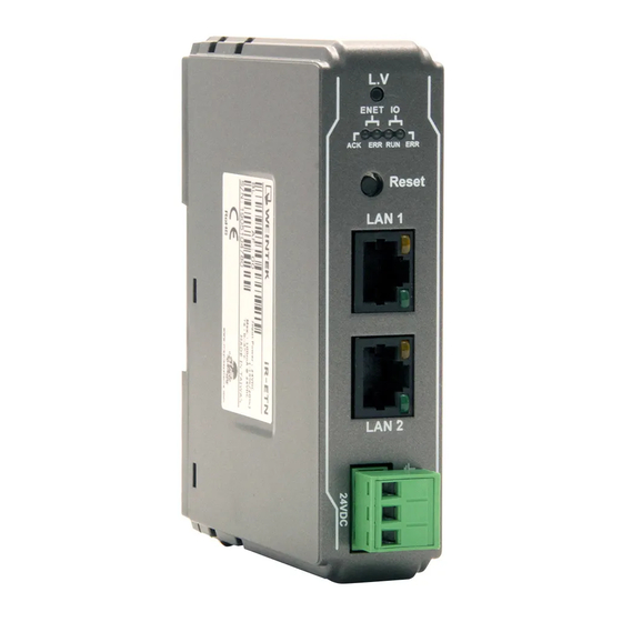
User Manual 1. Product Overview Reset Button Expansion Connector Ethernet Port LAN 1 Ethernet Port LAN 2 Power Connector... -
Page 6: Ir-Etn
User Manual 2. Specifications iR-ETN Communication Interface Specifications Model iR-ETN Depends on Power Consumption. Number of Bus Terminals Max. allowable number of iR modules is 16. Digital Input Point Max. 256 Expansion I/O Module Digital Output Point Max. 128 Analog Input Channel Max. -
Page 7: Led Indicators
User Manual 3. LED Indicators L.V LED L.V LED state Description 24V power normal Blinking Detect 24V power 24V power error *iR-ETN40R does not have L.V. LED. IO RUN/ERR LED RUN LED ERR LED Description Power off or no power... -
Page 8: Rj45
User Manual RJ45 Speed LED Operating as a 10-Mbps connection Green ON Operating as a 100-Mbps connection LINK /ACT LED No communication Orange There is activity on this port Blinking 4. RJ45 Interface RJ-45 Signal Name Descriptions Transmit +... -
Page 9: Modbus Mapping
User Manual 7. MODBUS Mapping Bit Mapping Start address Parameter Read/Write Function Code 0000~ Digital Input 0~511 Read 01FF Read 0000~ Digital Output 0~511 01FF Write 5,15 Register Mapping Start address Parameter Read/Write Function Code 0000~ Analog Input 0~255... -
Page 10: Ibus Information Register
: “iR-ETN” (ASCII) iBus Information Register Address Read/Write Data size Description 1word 10000 2710 Read Slot 0 iR-ETN Product code 1word 10001 2711 Read Slot 1 Module Product code 10001~ 2712~ Read 1word Slot 2~Slot 16 Module Product code... -
Page 11: Product Code List
User Manual module used. The maximum total data size of the registers is 500word. If the first module starts from address 20000 to 20499, then the second module starts from address 20500 to 20999, and so on. Address Read/Write... -
Page 12: The Default Value
User Manual is enabled or disabled. Enabling Error Mode will output an Error Value when an event occurs. Disabling Error Mode will keep the last value (for both digital and analog). Address Read/Write Data size Description 6100 17D4 Read/Write... -
Page 13: Device Error Code List
User Manual Device Error Code List Refer to special register address 5000/1388H Bit Number Description Bit0 Low power alarm Bit1 iBus initialization fault Bit2 Hardware error Bit3 Module lost connection Bit4 Module alarm Bit5 Number of iBus exceeds 16... -
Page 14: Ir-Pu01-P Nmt Control Address
User Manual iR-PU01-P NMT Control Address NMT Address State Value 0xFFF8(65528) Stop 0x0001 Operation 0x0002 Pre-operational 0x0080 Reset application 0x0081 Reset communication 0x0082... -
Page 15: In Modbus Mapping
User Manual 8. In Modbus Mapping The following is an example showing that when iR-ETN is connected with multiple modules, the address mapping and input/output bit mapping can be as follows: item Product Slot#1 iR-DI16-K Slot#2 iR-DQ16-P Slot#3 iR-DM16-P... -
Page 16: Digital Input Bit Mapping To Modbus
User Manual Digital Input Bit Mapping to Modbus Bit Offset Function Slot Module iR-ETN (0000h~0017h) Code Slot#1 iR-DI16-K 0000h~000Fh (Digital Input 0~15) Slot#2 iR-DQ16-P Slot#3 iR-DM16-P 0010h~0017h (Digital Input 0~7) Slot#4 iR-DQ08-R Digital Output Bit Mapping to Modbus Bit Offset... -
Page 17: Ir-Pu01-P Variable Instance Mapping
User Manual Channel 3 Output Mode 22503 …… …….. …… 16# Error Code 22516 iR-PU01-P Variable Instance Mapping Slot Module Description Address Function Code Axis 0 variable instance input 40000~40015 Slot#7 iR-PU01-P (Axis 0) Axis 0 variable instance output... - Page 18 User Manual Axis 0 variable instance output: Item Address Description Data Type Dec/Hex 40500 High Byte Axis 0 Mode of Operation USINT Unsigned 8 Low Byte Axis 0 Digital Output BYTE Unsigned 8 40501 Axis 0 Controlword UINT Unsigned 16...
-
Page 19: Ethernet/Ip Object
User Manual 9. EtherNet/IP Object Object List Name Object Type Object Code (Hex) Identity Standard Object Message Router Standard Object Assembly Standard Object Connection Manager Standard Object TCP/IP Interface Standard Object Ethernet Link Standard Object Module Register Manufacturer Defined Object... -
Page 20: Message Router Object
User Manual Message Router Object Class Code: 02 9.3.1 Class Attributes & Instance Attributes None Assembly Object Class Code: 04 Please refer to the EDS file generated by EasyRemote IO. Connection Manager Object Class Code: 06 9.5.1 Class Attributes & Instance Attributes... -
Page 21: Tcp/Ip Interface Object
User Manual Speed/ USINT Number of elements Duplex UINT Interface Speed Options USINT Interface Duplex Mode TCP/IP Interface Object Class Code: F5 9.7.1 Service Service Code Class Instance Name 0x0E ● ● Get Attribute Single 0x01 ● Set Attribute Single 9.7.2 Class Attributes... -
Page 22: Configuration Control
Data Type Value Slot# Module Read/Write Module Register# Register# The following is an example showing the mapping of Instance ID and Attribute ID when iR-ETN is connected to the following modules. Slot Module Name Slot#1 iR-AI04-VI Slot#2 iR-DQ16-P Slot#3 iR-DM16-P... -
Page 23: Ibus Object
User Manual Channel 1 Input Mode Channel 2 Input Mode Channel 3 Input Mode ……… ……… ……… Channel 0 Output Mode Channel 1 Output Mode Channel 2 Output Mode Slot#5 iR-AQ04-VI Channel 3 Output Mode ……… ……… ……… 16# Error Code For more information on registers, please see the user manual for each module. -
Page 24: Axis Register Object
User Manual Read/Write Digital Output Error UINT 0: Keep Last Value Mode (bit15-0) 1: Incorrect Value Read/Write Digital Output Error UINT Mode (bit31-16) ….. Read/Write UINT ….. Read/Write Digital Output Error UINT Mode (bit511-495) Read/Write Digital Output Error UINT... -
Page 25: Ibus Error Handling
User Manual 10. iBus Error Handling When communication with the module is lost, iR-ETN can report an error and stop module communication. The following actions can be taken: Set Special Register #10045 (273Dh) to 1 to ignore this error. -
Page 26: Power Consumption
User Manual 11. Power Consumption Type Device Consumption(5V) Power Supply(5V) iR-ETN 220mA/1.1w 2A/10w Coupler iR-COP 170mA/0.85w 2A/10w iR-ETN40R 526mA/2.63w 2A/10w iR-DM16-P 130mA/0.65w iR-DM16-N 130mA/0.65w iR-DQ08-R 220mA/1.1w Digital I/O iR-DQ16-N 205mA/1.02w iR-DQ16-P 196mA/0.984w iR-DI16-K 83mA/0.418w iR-AQ04-VI 65mA/0.325w iR-AI04-VI 70mA/0.35W Analogl I/O iR-AM06-VI 70mA/0.35W... -
Page 27: Ethernet Cascading
Last Ethernet port can be used as a diagnosis port 13. EasyRemoteIO EasyRemoteIO is an easy-to-use tool for configuring the parameters of iR-ETN. This tool can be found in the installation file of the latest version of EasyBuilder Pro. For... - Page 28 Select [Online] » [Change IP] to set the iR-ETN’s IP address. 4. Check Parameter with Monitor: Select [Online] » [Start Monitoring] or press Shift + M on the keyboard to activate the connection with iR-ETN. The device status and module status can be viewed via EasyRemoteIO.
- Page 29 User Manual 5. Export EtherNet/IP EDS file.
-
Page 30: Description File
User Manual 14. Description File When using iR-ETN, three types of description files can be generated in EasyRemoteIO. Weintek HMI Tag The exported tags can be used for Weintek HMI. For more information about exporting tags, see PLC Connection Guide -> Weintek Remote IO (MODBUS TCP/IP). - Page 31 User Manual 3. After importing the file, the iR-ETN added in CODESYS project can be found. Read/Write channels and initial parameters are built.
Need help?
Do you have a question about the iR-ETN and is the answer not in the manual?
Questions and answers