Table of Contents
Advertisement
Quick Links
Advertisement
Table of Contents

Related Manuals for Voltaire 4036 (QDR)


Summary of Contents for Voltaire 4036 (QDR)
- Page 1 Grid Director 4036 (QDR) / 2036 (DDR) August 2010 Doc P/N: DOC-00467 Doc Rev: A09...
- Page 2 The information in this document is furnished for informational use only, is subject to change without notice, and should not be construed as any commitment by Voltaire. Except as permitted by the applicable license, no part of this document may be reproduced, stored in a retrieval system, or transmitted in any form or by any means without the express written consent of Voltaire.
-
Page 3: Table Of Contents
Contents Contents ............................... iii Figures ..............................v Tables ............................... vi About this Manual ............................. vii Chapter 1. Introduction .......................... 1 4036/2036 Switch Overview....................... 2 4036/2036 Switch Main Features....................... 3 Management ............................4 Chapter 2. Unpacking ..........................5 Overview ............................6 Package Contents .......................... - Page 4 Contents Export Information ..........................30 Shipping Restrictions........................30 Chapter 6. Hardware Installation ......................31 Overview ............................32 Installation Options........................... 32 Cooling...........................32 Required Tools ..........................33 Site Planning ............................ 33 Rack and Clearance Requirements ..................33 Site Environment Specification....................34 Power Requirements ......................34 Site Preparation Checklist .....................34 Measuring the Distance between Mounting Rails................
-
Page 5: Figures
Figures Figure 1-1. 4036/2036 Front View ........................ 2 Figure 1-2. 4036/2036 Rear View ......................... 3 Figure 2-1. 4036/2036 Cardboard Package (Open) - Standard ..............7 Figure 2-2. Removing the 4036/2036 Switch from the Cardboard Package ..........8 Figure 2-3. Fixed Rail (KIT-00008) ....................... 9 Figure 2-4. - Page 6 Figures Figure 6-26. Securing the long bracket screws to the mounting bar ............47 Figure 6-27. Switch mounted in a rack – Rack front view................47 Figure 6-28. Replacing the Fan ........................48 Figure 6-29. Replacing the Power Supply ....................49 Figure 7-1.
-
Page 7: About This Manual
NOTE: Refer to the Voltaire release notes for last minute updates and restrictions Contact Us: Please send your documentation-related comments and feedback or report mistakes to: docs@Voltaire.com. - Page 8 Chapter 3 – Getting Started: Provides a description of the front and rear panels and of the product architecture, including a description of the various components. Chapter 4 – Product Options : Lists the Voltaire 4036/2036 configurations, provides examples of 4036/2036 in various clusters, and provides the necessary data for ordering a product configuration, as well as comprehensive technical specifications.
-
Page 9: Chapter 1. Introduction
Chapter 1. Introduction This chapter includes the following sections: 4036/2036 Switch Overview...................... 2 4036/2036 Switch Main Features....................3... -
Page 10: 4036/2036 Switch Overview
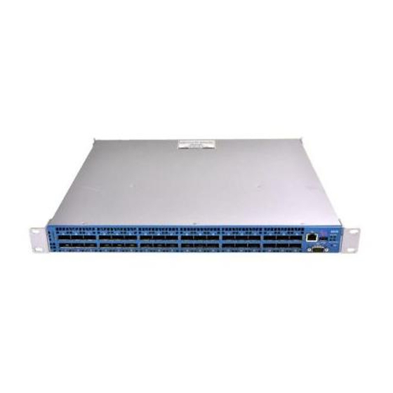
Introduction 4036/2036 Switch Overview The Voltaire Grid Director 4036/2036 is a high performance, low latency and fully non- blocking InfiniBand switch for high performance clusters. Delivering 2.88 Tbps of non- blocking bandwidth with less than 100 nanoseconds of latency (port-to-port), I/O bottlenecks are removed making applications operate at maximum efficiency. -
Page 11: 4036/2036 Switch Main Features
Introduction The following figure shows the rear view of a 4036 Unit. The rear view of the 2036 looks alike. Figure 1-2. 4036/2036 Rear View NOTE: The 2036 and 4036 switches are identical in appearance. Therefore, the graphic representations are generic and are applicable to either switch. 4036/2036 Switch Main Features Thirty-Six auto-negotiating QSFP InfiniBand ports in a 1U chassis: ›... -
Page 12: Management
CLI interface, routine tasks such as monitoring the switch’s operation or upgrading software and firmware are made simple. The Voltaire Grid Director 4036 comes with an onboard subnet manager, enabling simple, out-ofthe-box fabric bring-up for small to medium clusters. -
Page 13: Chapter 2. Unpacking
Chapter 2. Unpacking This chapter contains the following sections: Overview............................ 6 Package Contents ........................6 Unpacking the 4036/2036 Switch....................7 Rail Kit (KIT-00008)........................9 Multipurpose (Mng) Console Cable Kit ................... 10 Packing the 4036/2036 Switch ....................10... -
Page 14: Overview
Two power cords (one per power supply) Rail kit (see detail in Section 2.4) A multipurpose console cable kit (Mng) Voltaire Getting Started Guide (hard copy) A product CD containing 4036/2036 switch documentation and software Before unpacking, make sure that the box is sealed and undamaged. -
Page 15: Unpacking The 4036/2036 Switch
Unpacking Unpacking the 4036/2036 Switch This section details the 4036/2036 package contents and provides instructions on how to unpack the chassis. To unpack the 4036/2036 chassis, perform the following steps: Open the box and check that it contains the items as shown in Figure 2-1. Step 1 Figure 2-1. -
Page 16: Figure 2-2. Removing The 4036/2036 Switch From The Cardboard Package
Unpacking The iDataPlex Rail Kit and packaging are detailed in Appendix A. Remove the box containing the Rail Kit, the Power Cords, and the multipurpose console Step 2 cable kit (Mng). Remove the Getting Started Guide which also contains the Product CD. Step 3 Remove the top foam. -
Page 17: Rail Kit (Kit-00008)
Unpacking Rail Kit (KIT-00008) The rail kit entails: 2 Short Brackets (Angular bracket mount) 2 Long Brackets (Left and Right) 2 mounting bars 14 pan head Philips screws, 8-32 x 1/4" with tooth lock washers and nylon patch Figure 2-3. Fixed Rail (KIT-00008) Doc P/N DOC-00467 A09 4036/2036 Installation Manual Page 9... -
Page 18: Multipurpose (Mng) Console Cable Kit
Unpacking Multipurpose (Mng) Console Cable Kit The multipurpose console kit (Mng) contains: RJ45 to RJ45 cable A RJ45 to DB-9 cross-adaptor for RS-232 console connection (CLI). (The DB-9 adaptor has a number 26 printed on it. This means that pins 2 and 6 are crossed). A RJ45 to DB-9 adaptor for RS-232 console connection Figure 2-4. -
Page 19: Figure 2-5. Packing The 4036/2036 Switch
Unpacking Figure 2-5. Packing the 4036/2036 Switch Insert the switch into the carboard box and place it on the bottom foam. Step 6 Place the top foam on top of the switch. Step 7 Slide the rail kit box in the dedicated niche alongside of the switch, as shown in Figure 2-1. Step 8 IMPORTANT NOTE: When sending the switch for repair without the rail kit, it is still important to secure the it by filling this niche with a filler. -
Page 20: Chapter 3. Getting Started
Chapter 3. Getting Started This chapter contains the following sections: Overview..........................13 Front Panel Description......................13 Rear Panel Description ......................15... -
Page 21: Overview
Getting Started Overview The following sections provide a detailed description of the front and rear panels of the 4036/2036. Front Panel Description This section details the front panel 4036/2036 chassis. Figure 3-1. 4036/2036 Front Panel 1. Swappable power supply modules 2. -
Page 22: Table 3-1. 4036/2036 Front Panel Components
Getting Started The 4036/2036 front panel components from left to right are as follows: Table 3-1. 4036/2036 Front Panel Components 4036/2036 Component Function No. of components Power Supply 1 or 2 Provides the 4036/2036 DC supply. One or two AC/DC (PSU) (according to 100-240Vac to 12Vdc 350W hot-swappable redundant... -
Page 23: Rear Panel Description
Getting Started Rear Panel Description This section details the rear panel of a 4036/2036 chassis. Figure 3-2. 4036/2036 Rear Panel 1. 36 InfiniBand QDR (Quad Data Rate) ports using standard QSFP InfiniBand Connectors and LEDs supporting copper, active copper or optical cables. 2. -
Page 24: Table 3-2. Rear Panel Components
Getting Started The 4036/2036 rear panel components from left to right are as follows: Table 3-2. Rear Panel Components Component Function InfiniBand Port 4X QSFP InfiniBand connectors for passive copper cables, active Connector copper cables, active optical cables, and connect optical cables. InfiniBand Port Indicates the physical and logical status of each InfiniBand port. -
Page 25: Chapter 4. Product Options
Chapter 4. Product Options This chapter contains the following sections: 4036/2036 Switch Available Configurations................18 InfiniBand Clusters Using the 4036/2036 Switch ..............18 Ordering Information ....................... 20... -
Page 26: 4036/2036 Switch Available Configurations
The Voltaire Grid Director 4036/2036 is a 1U entry level 36 InfiniBand 4X ports switch, providing bidirectional 40 Gbps/20 Gbps per port grid connectivity, potentially serving as an edge switch in large fabrics (where the Voltaire 4036/2036 is serving as core switch) or as a standalone managed unit in smaller clusters. -
Page 27: Figure 4-3. Infiniband Cluster Using 4036/2036 Switch Triple-Hop Configuration
Product Options The following figures show a triple-hop non-blocking configuration, based on multiple 4036/2036 switches functioning as the cluster building blocks. 4036 #1 Server #1 4036 #5 4036 #2 Server #72 4036 #3 4036 #4 Figure 4-3. InfiniBand Cluster Using 4036/2036 Switch Triple-hop Configuration The following figures show another example of a three-hop non-blocking configuration, based on multiple 4036/2036 functioning as the cluster building block. -
Page 28: Ordering Information
Product Options Ordering Information Table 4-1. 4036/2036 Switch Ordering Information Number Name Description 2036 1U 36 port DDR Switch, front-to-back VLT-30113 Grid Director 2036 2PS cooling, dual PS 2036 1U 36 port DDR Switch, back-to-front VLT-30013 Grid Director 2036 2PS cooling, dual PS 2036 1U 36 port QDR Switch, front-to-back VLT-30114... -
Page 29: Table 4-3. 4036/2036 Switch Packing List (According To Configuration)
Product Options Table 4-3. 4036/2036 Switch Packing List (According to Configuration) Chassis PSU- Power KIT- KIT- CG-24 Cord Unit 1U Unit 1U 0008 0004 4036 (2 PS) VLT-30011 VLT-30111 4036 (1 PS) VLT-30112 VLT-30015 2036 (2 PS) VLT-30013 VLT-30113 2036 (1 PS) VLT-30114 Optional Doc P/N DOC-00467 A09... -
Page 30: Chapter 5. Technical Specifications And Certifications
Chapter 5. Technical Specifications and Certifications This chapter contains the following sections: 4036/2036 Switch Technical Specifications ................23 Power Specifications - Power Supply Module................. 24 Certifications..........................25 Gost-R Certification ......................... 26 Declarations..........................26 Label(s)............................ 27 Shock and Vibration ........................ 28 Chassis Clearance Requirements................... -
Page 31: 4036/2036 Switch Technical Specifications
Technical Specifications and Certifications 4036/2036 Switch Technical Specifications Table 5-1. 4036/2036 Switch Technical Data Features Details • Voltaire 19-inch front or rear rack mountable chassis, height: 1U, depth: 15” 4036/2036 - • 4036 with Quad Data Rate (QDR) 40 Gbps ports General •... -
Page 32: Power Specifications - Power Supply Module
Technical Specifications and Certifications Features Details • Physical 19-inch front or rear rack-mountable chassis Characteristics • Dimensions (H x W x D): 1.69 in. (43 mm) x 16.93 in. (430 mm) x 15 in. (381 mm) • Rail kit for rack mounting •... -
Page 33: Certifications
Technical Specifications and Certifications Attribute Specification Power Rating Power consumption*: 4036 - Maximum: 202W Typical: 152W (Numbers relate to copper cables. For optic cables add 1.5W per port.) 2036 - Maximum: 187W Typical: 141W (Numbers relate to copper cables. For optic cables add 1.5W per port.) BTU/hour = Watts x 3.413 Each optical adapter in use adds 1.5W max to the above... -
Page 34: Gost-R Certification
The Voltaire products comply with the Gost-R Russian safety regulations. Declarations Declaration of Conformity Voltaire products comply with the Radio & Telecommunications Terminal Equipment Directive 99/5/EEC, the EMC Directive 89/336/EEC, and of the Low Voltage Directive 73/23/EEC. Doc P/N DOC-00467 A09... -
Page 35: Hazardous Substances (Rohs 5) Compliance Declaration
Technical Specifications and Certifications Hazardous Substances (RoHS 5) Compliance Declaration Voltaire products comply with the RoHS directive under the exemption (RoHS 5) of lead in solders for servers, storage and telecommunication infrastructure. Label(s) The 4036/2036 label (example) below shows all safety and EMC text and logos. -
Page 36: Shock And Vibration
Technical Specifications and Certifications Figure 5-2. 2036 Label (Example) Shock and Vibration Prepare the 4036/2036 switch to ship in a rack by carefully following the rail kit installation and instructions, as detailed in Chapter 6. The 4036/2036 is susceptible to shock and vibration damage if the rail kit installation instructions are not followed precisely. -
Page 37: Weights And Dimensions
Technical Specifications and Certifications Weights and Dimensions Table 5-5. Unpacked Weights & Dimensions English Metric ( (lbs/in) kg/cm) Module Weight Weight 15.7 4.3* 4036/2036 Power 10.2 12.4 Supply 10.5 1 in = 2.54 cm 1 kg = 2.205 lbs * Including handles Table 5-6. -
Page 38: Export Information
Technical Specifications and Certifications Export Information CTP stands for Composite Theoretical Performance. It is a calculation measured in MTOPS (millions of theoretical operations per second) The 460EX/460GT contain a 440H6 core (not a 460 core; it is called 460 to distinguish it as a 90 nm core). -
Page 39: Chapter 6. Hardware Installation
Chapter 6. Hardware Installation This chapter contains the following sections: Overview..........................32 Installation Options........................32 Required Tools ........................33 Site Planning ........................... 33 Measuring the Distance between Mounting Rails ..............35 Assembling and Mounting the Rail..................35 4036/2036 Switch Power Up ....................48 Field Replaceable Units ...................... -
Page 40: Overview
Hardware Installation Overview This chapter describes how to prepare your site for installation and how to prepare and install the 4036/2036 switch. The 4036/2036 switch is a 19” rack mounted, 1U high chassis provided with a rail kit accommodating racks of different depths with a front-to-back distance between mounting rails of 26"... -
Page 41: Required Tools
Description Flat-blade screwdriver Phillips screwdriver Measuring tape Floating clip nuts (not provided by Voltaire) Phillips screws (not provided by Voltaire) Site Planning Planning the proper location and layout of your equipment rack or wiring closet is essential for successful 4036/2036 switch operation. Equipment placed too close together or in an inadequately ventilated area can cause overheating of the system. -
Page 42: Site Environment Specification
Section 5.1.1 . The 4036/2036 switch includes two hot-swappable redundant power supplies, providing full back-up purposes. Site Preparation Checklist To help prepare your site for installing the Voltaire 4036/2036 chassis, use the checklist in Table 6-2. Table 6-2. Site Preparation Checklist Task... -
Page 43: Measuring The Distance Between Mounting Rails
Hardware Installation Measuring the Distance between Mounting Rails To measure the distance between the rack mounting rails: Place the 4036/2036 chassis on a flat surface. Step 1 Using a measuring tape, measure the front-to-back distance between the rack vertical Step 2 mounting rails. -
Page 44: Table 6-3. Rail Kit (P/N Kit-00008) Detailed Part List
Hardware Installation The following table shows the list of items required for the installation of the fixed rail. Note that this only applies to Option 1 and 2. Option 3 (see Appendix A) entails different parts. Note: Item sizes are not proportional Table 6-3. -
Page 45: Option 1
Hardware Installation Option 1 The rail assembly described in this section enables front-to-rear switch installation within the rack, meaning that the front of the switch faces the front of the rack. The front of the switch is recessed 5 inches from the vertical rail of the rack to allow connecting the power cords from the front side of the rack. -
Page 46: Figure 6-1. 4036/2036 - Option 1 Assembly
Hardware Installation Figure 6-1. 4036/2036 – Option 1 Assembly NOTE: Standard rack clip nuts and rack screws are not provided. Doc P/N DOC-00467 A09 4036/2036 Installation Manual Page 38... -
Page 47: Figure 6-2. Mounting The Long Bracket
Hardware Installation To mount the 4036/2036 in a rack using Option 1: Put the chassis on a flat surface. Step 1 Mount the long bracket at the front of the chassis using three 8-32x1/4” pan head Philips screws. Important: Left and right long brackets are different. -
Page 48: Figure 6-5. Installing The Clip Nuts And Placing The Power Cord
U level (on all four vertical rack rails) as described in Measuring the Distance between Mounting Rails. Note: Rack clip nuts are not provided by Voltaire. Place the power cords with the female Step 6 connector facing the front of the rack (or the switch) with approximately 10”... -
Page 49: Figure 6-8. Securing Power Cords
Hardware Installation Secure each power cord with a cable Step 9 tie wrap so that you can still adjust the length of the cord if required. Figure 6-8. Securing power cords Connect the power cords to the switch Step 10 power supplies (PSU). -
Page 50: Figure 6-11. Mounting The Short Bracket
Hardware Installation Mount a short bracket from the inner Step 12 side of the mounting bar and fasten it using two 8-32x1/4” pan head Philips screws. At this stage, do not fully tighten the screws. Important: Use the lower holes in the short bracket as shown in the figure. -
Page 51: Option 2
Hardware Installation Figure 6-14. Switch mounted in a rack – Rack rear view Result – Rack front view Figure 6-15. Switch mounted in a rack – Rack front view Option 2 The rail assembly described in this section enables rear-to-front switch installation within the rack, meaning that the rear of the switch (InfiniBand connector side) faces the front of the rack. -
Page 52: Figure 6-16. 4036/2036 - Option 2 Assembly
Hardware Installation Figure 6-16. 4036/2036 – Option 2 Assembly NOTE: Standard rack clip nuts and rack screws are not provided. Doc P/N DOC-00467 A09 4036/2036 Installation Manual Page 44... -
Page 53: Figure 6-17. Mounting The Short Bracket
Hardware Installation To mount the 4036/2036 in a rack using Option 2: Put the chassis on a flat surface. Step 1 On each side of the chassis, mount the short brackets on the rear side of the switch (InfiniBand port side) using three 8-32x1/4”... -
Page 54: Figure 6-20. Securing The Rail
Align the short bracket holes with the Step 7 rack holes of the correct U level and secure them using two rack screws on each side (not provided by Voltaire). Figure 6-23. Secure the rack screws Doc P/N DOC-00467 A09 4036/2036 Installation Manual... -
Page 55: Figure 6-24. Installing The Long Bracket
On each side, align the long bracket holes with the rack holes of the correct U level and secure them using two rack screws (not provided by Voltaire) and two rail screws. Figure 6-24. Installing the long bracket Tighten the rack screws. (Rack screws... -
Page 56: 4036/2036 Switch Power Up
Once the 4036/2036 chassis is secure within the rack, electrical cables from the power distribution source can be fitted in preparation for connection. Two power cords are supplied by Voltaire, one per power supply unit. To power up the 4036/2036 switch:... -
Page 57: Power Supplies
Hardware Installation To replace the hot-swappable Fan module: Release the captive fasteners at each side of the fan and gently remove it from its slot. Step 1 Position the rear of the new fan in the slot. Step 2 Holding the fan level, slide it into the slot until it meets resistance at the chassis Step 3 connector. - Page 58 Hardware Installation Position the rear of the new power supply in the bay. Step 2 Holding the power supply level, slide it into the slot until it meets resistance at the chassis Step 3 connector. It should slide smoothly and easily. Push the module further until it is completely seated.
-
Page 59: Chapter 7. Cabling
Chapter 7. Cabling This chapter contains the following sections: Overview..........................52 Cabling Guide Bracket Installation ..................52 InfiniBand Cabling - QDR ......................55 Multipurpose Management (Mng) Console Cable..............56... -
Page 60: Overview
Cabling Overview This chapter provides details on the 4036/2036 switch cable guide brackets installation and cable management. Cabling Guide Bracket Installation NOTES: Selecting the optimal InfiniBand cable length depends on the overall cluster configuration and requires proper planning to produce orderly and maintainable cabling. The rack space for the 4036/2036 switch should be free from obstructions such as power strips. -
Page 61: Figure 7-2. Installing A Cabling Guide Bracket
Cabling To Install the Cabling Guide Brackets (CG-24): Install the Cabling Guide Bracket at the rear of the rack itself, on top or the rail bracket, Step 1 using two standard rack screws, as shown in Figure 7-2. Repeat on the other side. Step 2 Tighten the screws. -
Page 62: Figure 7-5. Cabling
Cabling Figure 7-5. Cabling Doc P/N DOC-00467 A09 4036/2036 Installation Manual Page 54... -
Page 63: Infiniband Cabling - Qdr
Cabling InfiniBand Cabling - QDR Selecting proper InfiniBand cable lengths depends on the overall cluster configuration and requires proper planning to produce orderly and maintainable cabling. We recommend dressing the cables from each row of QSFP connectors into two groups running them left and right, and fastening them down gently after connectivity was verified. -
Page 64: Multipurpose Management (Mng) Console Cable
Cabling Do not bend the InfiniBand cables too sharply. The minimum bend radius is 4” (10 cm). InfiniBand Cabling — Do’s and Don’ts Do not kink the cable Do not over-bend the cable behind the connector Do not twist the connector For Port Cable Specifications, refer to Appendix A. - Page 65 Cabling IMPORTANT: Both serial and Ethernet management ports of a 4036/2036 switch can be connected simultaneously. However, the Ethernet ports of the front and the rear panels cannot be connected simultaneously. To connect multi-purpose cable of a 4036/2036 switch: Connect the DB-9 connector and the RJ45 connector to each extremity of the multipurpose Step 1 console cable (Mng).
-
Page 66: Chapter 8. Operation
Chapter 8. Operation This chapter contains the following sections: Overview..........................59 Powering on the 4036/2036 Switch..................59 4036/2036 Switch LED Indicators ................... 60 Where to Go Next........................61... -
Page 67: Overview
Once the 4036/2036 chassis is secure within the rack, electrical cables from the power distribution source can be fitted in preparation for connection. Voltaire supplies two power cords, one per power supply unit. Doc P/N DOC-00467 A09 4036/2036 Installation Manual... -
Page 68: 4036/2036 Switch Led Indicators
Operation To start up the 4036/2036 switch: Ensure that all site power requirements have been met before connecting the chassis to a Step 1 power source. Before turning on the power, verify that the power supplies and fan tray are properly inserted. Step 2 At the rear of the 4036/2036 switch, plug the power cord into the power receptacle. -
Page 69: Where To Go Next
Eth tragic activity Where to Go Next Once you have verified that the 4036/2036 hardware is properly installed, it is ready for system configuration. To configure the system, refer to the Voltaire Switch User Manual. Doc P/N DOC-00467 A09 4036/2036 Installation Manual... -
Page 70: Chapter 9. Troubleshooting
Chapter 9. Troubleshooting This chapter contains the following sections: Overview..........................63 Solving Startup Problems......................63 Preparation before Contacting Customer Service ..............64... -
Page 71: Overview
Troubleshooting Overview This chapter provides suggestions for solving startup problems and useful information when contacting Voltaire’s Customer Service. Solving Startup Problems Try to solve startup problems using the 4036/2036 switch LED indicators. Case 1 Problem with power supply – How do I know that my power supply is not functional? Check the power cord and its connections. -
Page 72: Preparation Before Contacting Customer Service
Before you call, have the following information ready to help your service representative assist you as quickly as possible: Date you received the Voltaire 4036/2036 switch Chassis serial number (located on a label on the bottom of the chassis) Type of software and release number... -
Page 73: Appendix A Option 3 - Chassis Installation In An Idataplex Rack
Appendix A Option 3 – Chassis Installation in an iDataPlex Rack Unpacking the 4036/2036 Switch NOTE: Keep the original packing materials; they will be needed if: • The product needs to be moved. For example if it is staged at one location before being delivered at the production site. -
Page 74: Figure A-1. 4036/2036 Cardboard Package (Open) - Standard
Option 3 – Chassis Installation in an iDataPlex The 4036/2036 chassis is supplied in a box similar to the one shown in the following figure. To unpack the 4036/2036 chassis, perform the following steps: Open the box and check that they contain the items listed in the Packing List. Step 1 Figure A-1. -
Page 75: Mounting The Idataplex Kit
Option 3 – Chassis Installation in an iDataPlex Packing the Switch Refer to Packing the 4036/2036 Switch. Mounting the iDataplex Kit The 4036/2036 switch is a 19” rack mounted, 1U high chassis provided with a rail kit accommodating iDataplex racks with a front-to-back distance between mounting rails of 15.75"... -
Page 76: Figure A-2. 4036/2036 - Assembly In An Idataplex Rack
Option 3 – Chassis Installation in an iDataPlex Assembly in an iDataPlex Rack Figure A-2. 4036/2036 – Assembly in an iDataplex Rack NOTE: Standard rack clip nuts and rack screws are not provided. Doc P/N DOC-00467 A09 4036/2036 Installation Manual Page 68... -
Page 77: Figure A-3. Attaching The Mount Bracket
Option 3 – Chassis Installation in an iDataPlex To mount the 4036/2036 in an iDataplex rack: Put the chassis on a flat surface. Step 1 On each side of the switch, attach the mount brackets to the rear of the chassis (connector side) using two 8-32x1/4”... -
Page 78: Figure A-5. Securing Clip Nuts And The Mount Plates Onto The Rack
(into the clip nuts) using two screws. Note: Rack clip nuts and screws are not provided by Voltaire. Figure A-5. Securing clip nuts and the mount plates onto the rack Install the switch by inserting the... -
Page 79: Figure A-7. Securing The Front Of The Chassis
U level. Note: The Philips screws are not provided by Voltaire. Figure A-7. Securing the front of the chassis Connect the power cords to the power Step 6... -
Page 80: Appendix B Cabling Information
Appendix B Cabling Information This appendix provides cabling and port pinout information for the 4036/2036 switch. IB Port Cable Specifications Table 10-1 describes cabling specifications for the 4036/2036 4X InfiniBand ports. Table 10-2. 4X InfiniBand Port Cabling Specifications Type Maximum Cable Length 4XQDR Length (ft.) Length (m) -
Page 81: Gbe Ports (Management)
Cabling Information Type Maximum Cable Length 23.02 QSIBN-5600-7 19.7 QSIBN-5800-6 16.4 QSIBN-5300-5 13.1 QSIBN-5300-4 1 GbE Ports (Management) Use modular, RJ-45, straight-through UTP cables to connect the 10/100/1000 Fast Ethernet ports to external switches and routers. Use modular, RJ-45 cross-connect cables to connect to end systems. -
Page 82: Appendix C Qsfp Cable
Appendix C QSFP Cable QSFP Key Features: • Small size, high density, hot-pluggable connector with four transmit and four receive channels • Supports both types of cables: › Copper active or passive cable. Copper passive cable is equipped with two simple passive connectors and a standard copper cable. - Page 83 QSFP Cable Figure C-1. QSFP Connector-Dimensions NOTE: QSFP to CX4 cables are available to connect 4036/2036 equipped with QSFP with legacy DDR/SDR systems equipped with CX4 connectors. Overview Each of the 4036/2036 ports on the switch is equipped with transmit and receive circuit that can adjust to fit different types of link characteristics and either optical or copper cables.
- Page 84 QSFP Cable Figure C-2. QSFP Connector Doc P/N DOC-00467 A09 4036/2036 Installation Manual Page 76...
Need help?
Do you have a question about the 4036 (QDR) and is the answer not in the manual?
Questions and answers