Table of Contents
Advertisement
Quick Links
Jet Fuel 1A Conductivity Sensor
This manual covers the operational aspects of the D-2 JF-1A Conductivity Sensor. D-2
continuously strives to meet the full expectations of our customers and we welcome
comments on the structure, content and the ability of this manual to answer your
questions regarding our product. If you have any suggestions or comments please
contact us at Mail@D-2inc.com. This document is provided with the understanding that
future versions of this instrument may have additional commands, and the function of
the commands shown in this document may vary from the present operation.
Revision History
Revision
Description
2.0
Incorporated A440-010-FC, Application Note's 10-006, 10-007 as standard
elements, remove references to JFWIN, change to Hyperterminal
3.0
Correct Air/Zero Notations
JF-1A CONDUCTIVITY SENSOR
D-2 INCORPORATED
JF-1A
OPERATION MANUAL
REVISION 2.1
FIRMWARE VERSION 2.2
P/N A441-009
A440-009
FEBRUARY 2009
Date
Approved
15DEC10
A Fougere
28MAR11
A Fougere
Page 1 of 56
Advertisement
Table of Contents

Related Manuals for D-2 Incorporated JF-1A

Summary of Contents for D-2 Incorporated JF-1A
- Page 1 FIRMWARE VERSION 2.2 P/N A441-009 This manual covers the operational aspects of the D-2 JF-1A Conductivity Sensor. D-2 continuously strives to meet the full expectations of our customers and we welcome comments on the structure, content and the ability of this manual to answer your questions regarding our product.
-
Page 2: Table Of Contents
TABLE OF CONTENTS OPERATION MANUAL P/N A440-009 1.0 GENERAL 2.0 USAGE 3.0 FUNCTION 4.0 THEORY OF OPERATION 5.0 D-2 JF-1A SENSOR 6.0 MECHANICAL INSTALLATION 7.0 ELECTRICAL INSTALLATION 8.0 TEST PROCEDURE 9.0 SENSOR REMOVAL 10.0 SPECIFICATIONS 11.0 SERIAL DATA INTERFACE 12.0 CALIBRATION 13.0 COMPENSATED OUTPUT... -
Page 3: P/N A440-009
JF-1A CONDUCTIVITY SENSOR Appendix A: Service & Warranty Policy A440-009 Page 3 of 56 FEBRUARY 2009... -
Page 4: General
JF-1A CONDUCTIVITY SENSOR 1.0 GENERAL The D-2 JF-1A Conductivity Sensor is a reliable instrument for the continuous measurement of electrical conductivity of fuels. The JF-1A Conductivity Sensor incorporates innovative electronics Digital Signal Processing (DSP) techniques to accurately determine the electrical conductivity of fuel products. The instrument will measure fuel electrical conductivities between 0 and 2000 picosiemens/meter (pS/M), although it is optimized and normally used in the 0 to 500 pS/M range. -
Page 5: Usage
These additives are normally injected prior to transfer to the load vessel. The D-2 JF-1A Conductivity Sensor has the ability to monitor the electrical conductivity of fuel continuously, allowing its use as a sensing element in an automated additive injection system. -
Page 6: Theory Of Operation
4 Locking Collar 9 Installation Reference Plane 4.0 THEORY OF OPERATION The D-2 JF-1A Conductivity Sensor uses a probe consisting of two concentric stainless steel electrodes. When the probe is immersed in fuel, a very low frequency AC voltage is applied to the electrodes. Conduction through the fuel results in an AC electrical current that is amplified, detected, and output as either direct serial ASCII data, or as a standard 4-20 mA industrial current loop. -
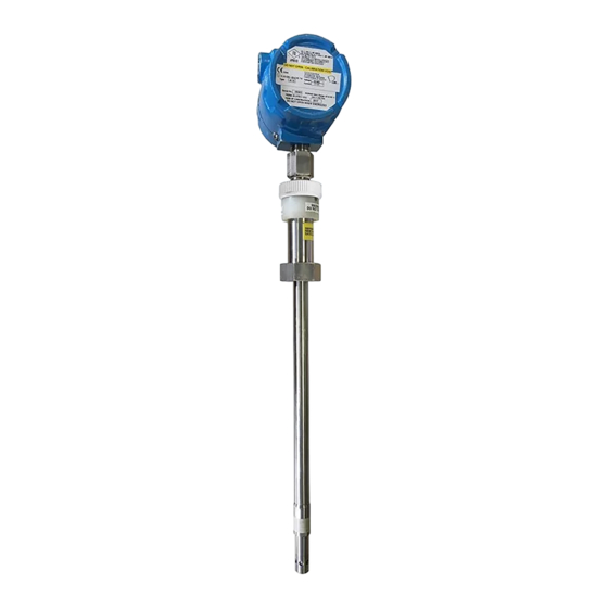
Page 7: Jf-1A Sensor
D-2 JF-1A On-Line Fuel Sensor With Retractable Mount The D-2 JF-1A Conductivity Sensor with Retractable Mount is shown in Figure 3. The unit is fully contained in a sealed approved housing. The sensor is designed to be fully intrinsically safe for operation in fuel facilities. The back cover allows for direct conduit connection to the meter and offers both 4 - 20 mA output and Serial Data Output Connections. -
Page 8: Mechanical Installation
The user MUST insure that additive will be completely mixed at the point at which the fuel is sensed by the JF-1A sensor. An in-line mixer can be used, or more conveniently the injection site can be followed by a pipe “T” or bend to cause turbulent flow mixing of additive. -
Page 9: Electrical Installation
JF-1A sensor may be activated. The 4-20 mA Loop supply open circuit voltage must be consistent with the “Open Circuit Supply” needs of the JF-1A at both its minimum and maximum indicating currents. The JF-1A has both input voltage limiting protection and polarity protection. - Page 10 In the figure below a typical loop wiring with by-pass capacitors is shown for the JF-1A sensor. The loop shows two sensing resistors in series with the JF-1A sensor. At the negative terminal of the Isolated Power Supply the “loop” is AC grounded using a capacitor.
- Page 11 JF-1A Conductivity Sensor PROPERLY BY- PASSED 4-20 mA INSTRUMENTATION JF-1 LOOP SENSOR SENSE BY-PASS 4-20 mA BY-PASS SENSE POWER SUPPLY GROUND SHUNT EARTH GROUND NOTE: Sensor wiring should be performed as defined by the National Electric Code (NEC), and ATEX sensor certificate.
- Page 12 JF-1A Conductivity Sensor 7.2 4 – 20 mA CONDUCTIVITY READINGS The following table details current output readings for the JF-1A sensor with a nominal 0-500 pS/M range representing 4 – 20 mA. (Please consult the factory for alternate range settings of the current output):...
- Page 13 JF-1A Conductivity Sensor 7.3 RS-232 CONNECTIONS Considerations (4-Wire) Figure 8A 4-WIRE ELECTRICAL CONNECTION DETAIL The 4 Terminal Screw Connector has both Power Input and RS-232/RS-485 Connections as listed in Table 1 below: TABLE 1 SCREW TERMINAL CONNECTION PIN DETAIL TERMINAL...
-
Page 14: Test Procedure
Consult computer manual for configuration and settings. Set Port for 9600 Baud. Confirm connection turning JF-1A sensor on, wake up banner should display on terminal screen. Pressing <CR> will result in a single frame of data being displayed on the screen (Note: Wait 5-10 seconds from power turn of JF- 1A). - Page 15 Set the sensor to send continuous data using the “SC” command entered from the Terminal. When the JF-1A is reporting values (less than 5 pS/M) the user can be satisfied that the sensor is clean. Readings on the screen should report less than 2 pS/M and should be stable.
-
Page 16: Sensor Removal
JF-1A Conductivity Sensor 9.0 SENSOR REMOVAL See Installation and Safe Use Manual for detailed mechanical removal instructions. 10.0 SPECIFICATIONS The electrical parameters are factory calibrated to 1% of reading. However, due to fuel measurement characteristics, the repeatability and reproducibility limits... -
Page 17: Serial Data Interface
EExd [ia] IIC T4/5/6 FM Certification UL Certification 11.0 SERIAL DATA INTERFACE The D-2 JF-1A has a comprehensive serial interface. The instrument contains no internal electrical adjustments. All instrument calibration constants and configurations are stored in internal non-volatile memory. The unit also has programmable output span range for the 4-20 mA output, allowing the user to customize the unit to a specific application. - Page 18 JF-1A Conductivity Sensor 11.1 RUN MODE When powered the unit commences operation in the “RUN MODE.” The unit sends the following sign on ASCII message at 9600 Baud, 8 Data Bits, No Parity and 1 Stop bit: (Note: Orator Text Used For All Instrument Outputs)
- Page 19 JF-1A Conductivity Sensor as calibration constants, or averaging settings, etc. The OPEN MODE can be attained by sending the “***O” command. The unit after entering open mode will send “OPEN MODE” when polled using a carriage return or line feed. From open mode the user can view all constants using the “RCAL”...
- Page 20 250 pS/M, or on a 0 – 500 pS/M configured sensor 12 milliamps. Readings and output currents for various range configured units is given in the table below. (Note, the JF-1A is normally configured for a 0 – 500 pS/M range equating to a 4 – 20 mA current range.)
- Page 21 JF-1A Conductivity Sensor Conductivity 0-500 pS/M * 0-1000 pS/M 0-2000 pS/M CURRENT mA CURRENT mA CURRENT mA 1000 1250 1500 1750 2000 11.4 CALIBRATION MODE In CALIBRATION OPEN MODE the unit collects data and outputs all raw data and processes measurements allowing a user to calculate operational constants.
-
Page 22: Calibration
JF-1A Conductivity Sensor (Note that the numbers above are examples only; actual values obtained will vary) 12.0 CALIBRATION CHECK (Also See A440-010-FC Manual, at the end of this documents) Note: Users of this section should be familiar with section 11.0 of this manual, Serial Commands. -
Page 23: Compensated Output
JF-1A Conductivity Sensor residuals will be left, eliminating the need to use the more exotic Toluene. When the JF-1A is reporting low values (less than 5 pS/M), the user can be satisfied that the sensor is clean. 12.3 CHECK SENSOR SCALE Place the sensor in a fuel with additive that is near the full-scale range of interest. -
Page 24: Filtered Output
14.0 FILTERED OUTPUT Boxcar (low pass filter) Average: The D-2 JF-1A Conductivity Sensor has a user specified filtered output. The output is box car averaged. The number of box cars can be set from 1 (no filtering) to 10 (maximum filtering). - Page 25 JF-1A Conductivity Sensor In the table below 63% and 90% response times are given for each box card setting. See Section 10.0 for setting the box car number constant n. A440-009 Page 25 of 56 FEBRUARY 2009...
- Page 26 Window Filter “W”. This Window filter can be used with or without N set. Essentially the window filter limits the rate at which the JF-1A sensor output can change from scan to scan. W has units pS/cm/scan, and can be set from 0 –...
-
Page 27: Maintenance
15.2 Cleaning The JF-1A Conductivity Sensor should be cleaned every 6 months of use. Fuel additives or particulate may build up on the sensor, degrading its performance. The sensor can be cleaned using the same procedure found for checking the instrument Zero in the previous sections. -
Page 28: Optional 2-Wire Temperature Interface
JP2 Terminals. These are “snap” out Molex screw terminals which can be removed to assist in wiring. Cabling used should be in compliance with the JF-1A Ex examination certificate. The 2 wire temperature interface is “polarity insensitive”. - Page 29 Electric Code (NEC), and ATEX sensor certificate. 14.2 4 – 20 mA Temperature Readings The following table details current output readings for the JF-1A sensor with a nominal -10 to 60 Celsius range representing 4 – 20 mA. (Please consult the...
- Page 30 JF-1A Conductivity Sensor APPENDIX A: LIMITED WARRANTY One year from date of shipment, D-2 Incorporated, guarantees its products to be free of defects in materials and workmanship. In the event a product malfunctions during this period, the company obligation is limited to repair of the defective item at our factory, or the defective item may be replaced at our option.
- Page 31 The customer will be required to obtain a return authorization number from Customer Service at D-2 Incorporated prior to the return of the instrument. This number should be displayed on the outside of the container, preferably on the shipping label, and included on the shipping documentation sent with the instrument.
- Page 32 REVISION 1 P/N A440-010 - FC This manual covers field calibration of the D-2 JF-1A Conductivity Sensor. D-2 continuously strives to meet the full expectations of our customers and we welcome comments on the structure, content and the ability of this manual to answer your questions regarding our product.
- Page 33 The user should have a general knowledge of process control instrumentation, serial data, standards, tolerances, and mathematics prior to attempting a field calibration of the JF-1A Sensor. If the use has any doubt or confusion in relation to an applied field calibration the sensor MUST not be placed back into service until corrected.
- Page 34 3.2 ESTABLISH SERIAL DATA COMMUNICATION WITH JF-1A With PC or terminal connected to serial data port of JF-1A turn on instrument power and validate that “power up” banner is received from the unit. Request data from the unit after 10 seconds and confirm data responses are received to validate serial data out connection to instrument.
- Page 35 Scale”, otherwise perform section 3.4 Reset Zero. 3.4 RESET INSTRUMENT ZERO READING a) Note the value read with unit in air, as example JF-1A reading 4.3 pS/M, the offset is high by 4.3 pS/M (label OFFold). b) Place the unit in open mode by sending the “***O” command.
- Page 36 JF-1A Conductivity Sensor e) Read the current slope constant by sending the “FS” command (label as FS- old). f) Mathematically determine the new FS-new = C-old/C-std* FS-old. g) Enter new calibration value using command “FS=FS-new”. h) Check by returning to run mode using the ***R command.
- Page 37 JF-1A Conductivity Sensor 20.0 5.00 Equipment Required: a) JF-1 Serial Test Cable FSI P/N B440-079 b) Serial Data Communicating Device, set for operation at 9600 baud, 1 stop, 8 data, No parity c) 250 ohm sensing resistor d) Digital Multi Meter with 0.001 VDC resolution.
- Page 38 DAF by sending “DAF=820”. To test this value we need only to set conductivity to our desired full- scale value by sending “Cond=700” to the JF-1A unit. Read the Digital Voltage Meter output that should be connected across either the 250 or 100-ohm sense resistor.
- Page 39 Serial Data Ports are used simultaneously Background In some applications of the JF-1A both the current ports and serial data ports are used. In these applications the user must take care to ensure that input voltage ratings are not exceeded and that power supplies do not create multiple ground paths through the instrument.
- Page 40 Power input to the JF-1A is required in order for the instrument to operate properly. If multiple output data sources from the JF-1A are to be used then the sensor needs multiple power inputs. In all cases, it is very important that power inputs are wired correctly to the JF-1A;...
- Page 41 JF-1A Conductivity Sensor +24 VDC ISOLATED POWER SUPPLY - GND PLC CURRENT DETECTOR A440-009 Page 41 of 56 FEBRUARY 2009...
- Page 42 (convert the current to a voltage in the PLC). As in example 1 the JF-1A derives its power for its operation from the loop current supply. Note both the supply and loop current detector are normally isolated from ground.
- Page 43 (convert the current to a voltage in the PLC). As in example 1 the JF-1A derives its power for its operation from the loop current supply. Note both the supply and loop current detector are normally isolated from ground.
- Page 44 JF-1A Conductivity Sensor connection between the two loops then the virtual loop connection is corrupted and neither loop current will be correctly set by the JF-1A, and, under extreme circumstances may result in damage to the JF-1A current output devices.
- Page 45 Section 1.0 Method of Adjustment 4-20 mA output span JF-1 Sensor Conductivity: The JF-1 Sensor can be used with fuel conductivities from 0 – 2000 pS/M (Note JF-1A- MA 0 – 200,000 pS/M). Normally the sensor has the 4-20 mA output scaled for a specific range which allows the user to optimize the interface for a specific application.
- Page 46 JF-1A Conductivity Sensor Table 1 Reading Current mA Voltage 100 Voltage 250 ohm Sense Ohm Sense 1.00 1.25 12.0 2.50 16.0 3.75 20.0 5.00 Section 2.0 Current Loop Calibration using DVM and Reference Resistors: Note: if the user can read conductivity values directly from his PLC then it is...
- Page 47 JF-1A Conductivity Sensor c) Connect the serial cable to the test jack on the JF-1 Sensor. On the PC press enter and confirm connection is made by the receipt of a single line of data from the JF-1 Sensor. (Or turn the unit on add see the turn on banner being received).
- Page 48 JF-1A Conductivity Sensor must re-send the “Cond=1000” each time an adjustment is made to change the current output.) i) After steps 5 – 6 are complete the user should now check the “low end of the range to ensure the slope adjustment has not resulted in “significant errors of the...
- Page 49 Serial Data Communicating Device, set for operation at 9600 baud, 1 stop, 8 data, No parity m) PLC Connected to JF-1A Current Output with ability of the operator to read the value directly in pS/M from the PLC. Procedure: a) Connect the probe to the PLC.
- Page 50 JF-1A Conductivity Sensor g) To test this value we need only to set conductivity to our desired full-scale value by entering into the JF-1A the value we want it to output in equivalent current. This is done by entering “Cond=1000” to the JF-1 unit.
- Page 51 -20˚C - 60˚C representing the output range of 4 – 20 mA. This is detailed in Table 2 below: *WARNING: CONSULT THE SAFE USE MANUAL FOR SAFE AMIBENT OPERATING CONDITIONS FOR THE JF-1A SENSOR. THE TEMPERTURE RANGE LISTED ABOVE IS THE THORETCAL RANGE OF THE TEMPERATURE ELECTONICS, NOT THE SAFE USABLE RANGE.
- Page 52 100 or 200-ohm sense resistor to the temperature loop terminals. 2) Power the JF-1A either from the conductivity loop or from the 4 –wire connection port (Note the power supply must be isolated from the supply which is used to run the sensor see application not 10-006).
- Page 53 JF-1A Conductivity Sensor key, the JF-1 will respond with the words “OPEN MODE”. 6) Read the current offset value TRL, enter the request “TRL” the unit will return “TRL=-20, where “-20”is the current setting, as we want to change the lowest value to b 0˚C we need to change TRL to = 0, enter the...
- Page 54 Serial Data Communicating Device, set for operation at 9600 baud, 1 stop, 8 data, No parity u) PLC Connected to JF-1A Current Output with ability of the operator to read the value directly in pS/M from the PLC. Procedure:...
- Page 55 TDAF = 63.5, This value is temporarily entered into DAF by sending “DAF=63.5”. 24) To test this value we need only to set temperature to our desired full-scale value by entering into the JF-1A A440-009 Page 55 of 56 FEBRUARY 2009...
- Page 56 JF-1A Conductivity Sensor the value we want it to output in equivalent current. This is done by entering “Temp=50” to the JF-1 unit. 25) Read the PLC reading, this reading should equal 50˚C. If this is not attained TDAF needs to adjusted, increase the value of TDAF if the reading is low, decrease the value if the voltage is high.
Need help?
Do you have a question about the JF-1A and is the answer not in the manual?
Questions and answers