Table of Contents
Advertisement
Quick Links
Advertisement
Table of Contents

Summary of Contents for WOBIT MD150A
- Page 1 MD150A Manual Digital process display 0-10V, 4-20mA Programmable indicator for sensors with current, voltage or potentiometer output P.P.H. WObit E.J.K. s.c. Dęborzyce 16, 62-045 Pniewy tel.48 61 22 27 422, fax.48 61 22 27 439 e-mail: wobit@wobit.com.pl www.wobit.com.pl...
-
Page 2: Table Of Contents
Based on the information should not be inferred a certain features or suitability for a particular application. This information does not release the user from the obligation of own judgment and verification. P.P.H. WObit E.K.J. Ober S.C. reserves the right to make changes without prior notice. -
Page 3: Safety And Assembly Rules
• Avoid routing control (signal) cables in parallel with or in close vicinity of power and supply cables. • Avoid close vicinity of devices generating high level of electromagnetic and/or pulse interference (high power loads, loads with phase or group power regulation). www.wobit.com.pl Manual -MD150A – 27.10.2014 – v.1.2 page 3... -
Page 4: Device Description
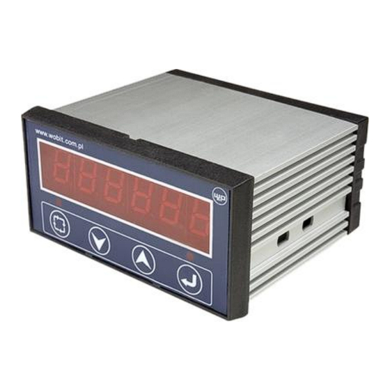
10000 measurement steps for the range of 0-10V. The measurement result is presented on six position display. Apart from measurement output MD150A has 2 relay outputs which can be freely configured for switching on/off at specified thresholds. The device is also equipped with universal digital inputs which can be used for external triggering of measurements and for “pausing”... -
Page 5: Description Of Interfaces And Front Panel
9,10 PK1 (NO) relay contacts 11,12 PK2 (NO) relay contacts 12-36 VDC power supply, min. 250mA Power supply ground Connections diagram Fig. 1 Example of connections of external signals to MD150A. www.wobit.com.pl Manual -MD150A – 27.10.2014 – v.1.2 page 5... -
Page 6: Menu Description
6 positions of the display). In order to display older part of the result, press Exceeding of measurement range (10V or 20mA) results in blinking of the displayed value www.wobit.com.pl Manual -MD150A – 27.10.2014 – v.1.2 page 6... -
Page 7: Example Of Parameter Change
0-20mA (e.g. 4-20mA) set 0-20mA mode. 4.2 Configuration of measurement units MD150A process display enables converting the sensor signal into values in measurement units specific for a given sensor. This allows for indication of e.g. measurement value in meter for distance meter, inclination for inclinometer or pressure in bar for pressure sensor. -
Page 8: Number Of Decimals Of The Result/Parameters
10V after 1 sec. (100Hz/99 ->”1). 5. Configuration of relay output MD150A indicator has 2 relay outputs PK1 and PK2 which can be switched on/off depending on current measurement value. The following parameters are used for relay outputs configuration: 1. -
Page 9: Digital Input Din1, Din2
DIN1 input, i.e. change of the signal status from 0V to +5..+24V. DIN2 input is used for “freezing” of a current measurement on the MD150A indicator display. The last measured value is displayed (blinks) until DIN2 input reaches high status (+5...+24V). -
Page 10: Usb And Rs485 Modbusr Interface
Readout of X registers 5 (0x05) Record of single bit Type of variables used Variable name Description Size Number of occupied registers (Bytes) WORD Complete number with a sign REAL Floating point number www.wobit.com.pl Manual -MD150A – 27.10.2014 – v.1.2 page 10... - Page 11 Number of Lo registries 0x02 Register 0x03 Hi REAL (Byte 3) CRC Hi 0x65 Register 0x03 Lo REAL (Byte 2) CRC Lo 0xCB CRC Hi 8 bit CRC Lo 8 bit www.wobit.com.pl Manual -MD150A – 27.10.2014 – v.1.2 page 11...
-
Page 12: Technical Parameters
Display Housing Height : 45 Width: 92 mm Length : 81 mm Weight 200g IP40, from panel head - IP65 Leak tightness degree Universal password 3145 FSR – full scale range www.wobit.com.pl Manual -MD150A – 27.10.2014 – v.1.2 page 12...

Need help?
Do you have a question about the MD150A and is the answer not in the manual?
Questions and answers