Table of Contents
Advertisement
Quick Links
Advertisement
Table of Contents

Related Manuals for Stevens HydraProbe

Summary of Contents for Stevens HydraProbe
- Page 1 ® Soil Sensor Installation Guide Rev. IV For Firmware Version 6.0 DOC# HP008A...
- Page 2 USER INFORMATION Stevens makes no warranty as to the information furnished in these instructions and the reader assumes all risk in the use thereof. No liability is assumed for damages resulting from the use of these instructions. We reserve the right to make changes to products and/or publications without prior notice.
- Page 3 1907/2006/EC REACH Stevens Water Monitoring Systems, Inc. certifies that the Stevens HydraProbe, including all models and components, are compliant with the European Union Regulation (EC) 1907/2006 governing the Registration, Evaluation, Authorization, and Restriction of Chemicals (REACH) and do not contain substances above 0.1% weight of a Substance of Very High Concern (SVHC) listed in Annex XIV as of June 15th, 2019.
- Page 4 Supporting Documents Document Number Document HP003A HydraProbe Quick Start, SDI-12 HP004A Soil Data Guide HP005A HydraProbe Install and Troubleshooting Guide HP006A HydraProbe Quick Start, RS-485 HP007A Regulatory Information HP008A HydraProbe Comprehensive Manual HP009A Soil Geomorphology Guide for Soil Sensors...
-
Page 5: Table Of Contents
Installation Precautions ..........................14 Topographical Station Placement Considerations ..............14 Soil Sensor Depth Selection ...................... 16 Installation of the HydraProbe in Soil ..................18 2.4.1 Checklist before you go into the field ................18 2.4.2 Test the probes and logger in the office before going into the field ........ 18 2.4.3... - Page 6 Appendix A– HydraProbe SDI-12 Communication (6.0 Firmware) Appendix B- HydraProbe RS-485 Communication (6.0 Firmware) Appendix C– Custom Calibration Programming Custom Calibration Procedure for the SDI-12 HydraProbe ............... 37 Custom Calibration Settings Procedure for the RS-485 HydraProbe ..........39 Appendix D - Useful links DOC# HP008A...
-
Page 7: Introduction
HydraProbes installed more than a decade ago are still in service today. The HydraProbe is not only a practical measurement device; it is also a scientific instrument. Trusted by farmers to maximize crop yields, using HydraProbes in an irrigation system can prevent runoff that may be harmful to aquatic habitats, conserve water where it is scarce, and save money on pumping costs. -
Page 8: Applications
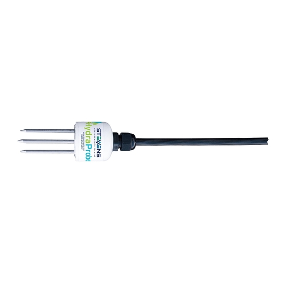
Structural Components There are three main structural components to the HydraProbe: the tine assembly, body, and cable. The marine grade stainless steel tine assembly is the four metal rods that extend out of the base plate ground plane and is the wave guide. -
Page 9: Accuracy And Precision
Accuracy and range of Bulk EC depends on soil properties and distribution of ions present. Electromagnetic Compatibility The Stevens HydraProbe is a soil sensor that uses low power RF energy. The intended use of the HydraProbe is to be buried in soil underground to depths ranging from 5 cm to 2 meters deep. -
Page 10: Soil Data Accessories And Other Products
All configurations provide the same measurement parameters with the same accuracy. The underlying physics behind how the HydraProbe works and the outer construction are also the same for each configuration. Table 1.2 provides a physical description of the HydraProbe. -
Page 11: Tempe Cell
In addition to the soil-specific calibration and validation, an algorithm can be developed to determine the soil’s matric potential using the HydraProbe up to 2 bars of tension. The Stevens Tempe Cell is ideal for mesonets, climate reference networks, and soil monitoring stations. See Appendix C. -
Page 12: Hydraprobe Versions
Celsius and is suitable for artic and cold climate deployments. Parameter Unit Soil Moisture Water fraction by volume Bulk EC Temperature Corrected Temperature Temperature Bulk EC Real Dielectric Permittivity Imaginary Dielectric Permittivity Pore Water EC Dielectric Loss Tangent Table 1.3. HydraProbe Parameters DOC# HP008A... - Page 13 56012-04-30 SDI-12, Professional, w/100 ft. cable 56012-06 SDI-12, Professional (Extended Temp), w/100 ft. cable 56012-06-30 Table 1.4 Stevens part numbers for SDI-12 HydraProbes Manufacturer Part # Description RS485, Professional, w/25 ft. cable 56485-02 RS485, Professional (Extended Temp), w/25 ft. cable 56485-02-30 RS485, Professional, w/50 ft.
-
Page 14: Installation
DO NOT place more than one probe in a bucket of wet sand while logging data. More than one HydraProbe in the same bucket while powered may create an electrolysis effect that may damage the probe. - Page 15 If the water table rises to the depth of the HydraProbe, the HydraProbe soil moisture measurements will be at saturation and will be indicative of the porosity. If you are interested in groundwater level measurements in wells, a water depth sensor might provide the necessary information.
-
Page 16: Soil Sensor Depth Selection
For those in agriculture, two to three HydraProbes may be installed in the root zone and one HydraProbe may be installed beneath the root zone; this would also be dependent upon the crop and root zone depth. The amount of... - Page 17 on the USDA’s soil survey page. More information about the soil horizons in your area can be found Soil Horizon Property Decaying plants on or near surface Top Soil, Organic Rich Subsoil, Most Diverse Horizon and the Horizon with the most sub classifications Leached Horizon (light in color) Weathered/aged parent material Table 2.1 Basic description of soil horizons.
-
Page 18: Installation Of The Hydraprobe In Soil
Use a paint scraper to smooth the surface of the soil where it is to be installed. The soil must be flush with the base plate. If there is a gap, the HydraProbe signal will average the gap into the soil measurement and create errors. -
Page 19: Soil Sensor Orientation
Figure 2.6 HydraProbe Installed in undisturbed soil. Push the tines of the HydraProbe into the soil until the base plate is flush with the soil. The tines should be parallel with the surface of the ground. Do not rock the probe back and forth because this will disturb the soil and create a void space around the tines. -
Page 20: Wiring To A Logger Station
Wiring to a Logger Station Connect the red wire to a +12 volt DC power supply and connect the black wire to the ground for all HydraProbe models. The measurement duty cycle is 2 seconds. Wiring and power for HydraProbes... -
Page 21: Lightning
After a few months, the backfilled soil will begin to compact on its own and return to a steady state bulk density. The HydraProbe will effectively be residing in two soil columns. The tines will be in the undisturbed soil column, and the head, cable and conduit will be in the backfill column that is undergoing movement. - Page 22 Figure 2.9 Ground the logger station with dual dissipators and ground rod DOC# HP008A...
-
Page 23: Troubleshooting And Soil Considerations
3.1.1 Check Wiring and Power If you are unable to get a response from the HydraProbe, first physically check wire connections from the probe to the logger. Verify the cable has no cuts or abrasions. Use a handheld voltmeter to check the voltage on the battery and the SDI-12 bus. -
Page 24: Check The Logger Configuration
Please note that the soil that resides between the tine assembly is where the measurements are taken. If there is a void space in the soil between the tines, this will affect the hydrology where the HydraProbe is taking measurements. If the void space is saturated with water, it will increase the soil moisture measurement. If the void... -
Page 25: Evapotranspiration
Figure 3.1 shows the measurement volume where the HydraProbe takes measurements and a void space between the tine assembly. These void spaces can occur from a poor installation such as rocking the probe side to side or not fully inserting the probe into the soil. -
Page 26: Shrink/Swell Clays
If a fissure forms in the measurement volume of the HydraProbe, the probe will signal average the air gap caused by the fissure into the reading and potentially generate biased results. If the fissure fills with water, the soil moisture measurement will be high, if the fissure is dry, the soil moisture measurement will be lower than expected. -
Page 27: Salt Affected Soil And The Loss Tangent
While the HydraProbe cable is direct burial grade and is resistant to animal bites, the cable leading to the probe may be a tasty treat for some animals. If communication between the logger and the probe fails, check the cable for damage. - Page 28 Figure 3.2 Soil Ped Types. 3.2.9 Frozen Soil The HydraProbe can be used to determine if soil is frozen. Once ice reaches 0 Celsius, it will begin to thaw, and the real dielectric permittivity will increase from 2.5 to 5. The temperature alone may not indicate whether the soil is frozen.
- Page 29 Appendix A– HydraProbe SDI-12 Communication (6.0 Firmware) SDI-12 communication protocol allows compatible devices to communicate with each other. More information 4.1, 4.0, 3.0, 2.8 and 2.7 firmware versions have a different array about SDI-12 can be found at http://www.sdi-12.org/. of commands. Contact Stevens Water for more information.
- Page 30 12 – SDI-12 protocol version STEVENSW – Manufacturer nnnnn – Part number v.vvv – Firmware version c – Calibration xxxxxxxx – Serial number Measurements SDI-12 Command Response Description Request Measurement a – Sensor address ttt – seconds (000 – 999) until the atttn measurement is ready n –...
- Page 31 The following tables list the values and units: Selector Order Parameter Unit Soil Moisture Water fraction by Volume (wfv) Soil Temperature Celsius (C) Soil Temperature Fahrenheit (F) Bulk EC Siemens/Meter (S/m) (Temperature Corrected) Bulk EC Siemens/Meter (S/m) Pore Water EC Siemens/Meter (S/m) Real Dielectric Permittivity Imaginary Dielectric Permittivity...
- Page 32 485 can operate with up to 3000 ft of cable. The disadvantage compared to SDI-12 is that RS-485 does draw more power. Broadcast address: “///” if there is a single probe on the bus. 4.1, 4.0, 3.0, 2.8 and 2.7 firmware versions have a different array of commands. Contact Stevens Water for more information. Model Numbers Version Part # Suffix Professional, w/25 ft.
- Page 33 Identification RS-485 Command Response Description Access Level aaaXR_SN aaa<Serial Number> Read Serial Number Read Only aaaXR_FV aaa<Firmware Version> Read Firmware Version Read Only aaaXR_MN aaa<Model Number> Read Model Number Read Only Measurement RS-485 Command Response Description Access Level aaaTR Request Measurement Read Only aaaT<0-1>...
- Page 34 Pore Water Offset RS-485 Command Response Description Access Level aaaXR_PWOS aaa<Current Offset> Read Pore Water Offset Read Only aaaXR_PWOS_<New Offset> aaa<New Offset> Write Pore Water Offset Write Only Reset Pore Water Offset to aaaXD_PWOS aaa+3.4 Write Only default 3.4 DOC# HP008A...
- Page 35 The following extended commands will change the coefficients in one of two general formulas that translate the real dielectric permittivity to soil moisture. In many cases, the HydraProbe will not need to be recalibrated in most mineral soils. The default General calibration has been heavily reviewed and will provide reasonable accuracy for most applications.
- Page 36 The coefficients for equations [C1] and [C2] can be programmed into the firmware of the HydraProbe. Below is a procedure for programming a custom calibration on a RS-485 or SDI-12 HydraProbe. Development of a new calibration involves collecting soil samples and drying them down in a gravimetric analysis.
- Page 37 Custom Calibration Procedure for the SDI-12 HydraProbe Note: We recommend to first post process a new calibration for a period of time before programming the coefficients into sensors. We also recommend logging the real dielectric permittivity so that a data set can be recalibrated if needed.
- Page 38 The CUSTOM 1 formula uses four coefficients, so we will need to assign the values to them. To assign a value of -10.0 to the first coefficient, a value of 5.0 to the second, 0.3 to the third and 0.0005 to the fourth we would enter these commands.
- Page 39 Custom Calibration Settings Procedure for the RS-485 HydraProbe Note: We recommend to first post process a new calibration for a period of time before programming the coefficients into sensors. We also recommend logging the real dielectric permittivity so that a data set can be recalibrated if needed.
- Page 40 000XW_COEF_E_0.3<CR><LF> 000XW_COEF_F_-0.6<CR><LF> To verify that your settings have been programmed into the probe, enter the following query commands. The probe should respond as shown in bold: 000XR_COEF<CR><LF> 000+00.00000000+00.02240000-00.00047000+00.00000514+00.30000001-00.60000002 The values that the probe returns may be slightly different than the values you entered. This is an artifact of the conversion from decimal to binary and then back again.
- Page 41 Appendix D - Useful links Stevens Water Monitoring Systems, Inc. www.stevenswater.com The Soil Science Society of America http://www.soils.org/ The US Department of Agriculture NRCS Soil Climate Analyses Network (SCAN) http://www.wcc.nrcs.usda.gov/scan/ The US Department of Agriculture NRCS Snotel Network http://www.wcc.nrcs.usda.gov/snow/ The US Bureau of Reclamation Agricultural Weather Network (AgriMet) http://www.usbr.gov/pn/agrimet/...
Need help?
Do you have a question about the HydraProbe and is the answer not in the manual?
Questions and answers