Table of Contents
Advertisement
Available languages
Available languages
Quick Links
Betriebsanleitung
Speisegerät SINEAX B 811
Mode d'emploi
Source d'alimentation SINEAX B 811
Operating Instructions
Power pack SINEAX B 811
B 811-1 B d-f-e
999 469
09.99
Aargauerstrasse 7
CH-5610 Wohlen/Switzerland
Telefon +41 56 618 21 11
Telefax +41 56 618 24 58
Camille Bauer AG
Telex 827 901 cbm ch
1
Advertisement
Chapters
Table of Contents

Summary of Contents for Camille Bauer Gossen MetraWatt SINEAX B 811
- Page 1 Source d’alimentation SINEAX B 811 Operating Instructions Power pack SINEAX B 811 B 811-1 B d-f-e 999 469 09.99 Aargauerstrasse 7 CH-5610 Wohlen/Switzerland Telefon +41 56 618 21 11 Telefax +41 56 618 24 58 Camille Bauer AG Telex 827 901 cbm ch...
- Page 2 Betriebsanleitung Speisegerät SINEAX B 811 .......... Seite 3 Mode d’emploi Source d’alimentation SINEAX B 811 ......Page 13 Operating Instructions Power pack SINEAX B 811 ........... Page 23 Sicherheitshinweise, die unbedingt beachtet wer- den müssen, sind in dieser Betriebsanleitung mit folgenden Symbolen markiert: Les conseils de sécurité...
-
Page 3: Table Of Contents
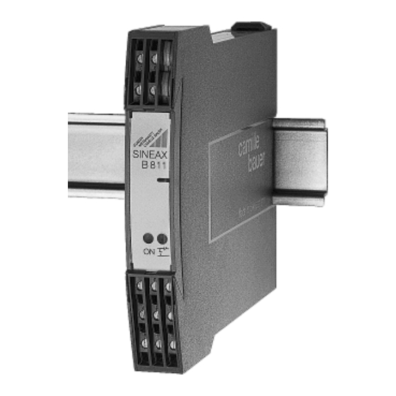
Ausgangssignal lineares Verhalten Aargauerstrasse 7 CH-5610 Wohlen/Switzerland Telefon +41 56 618 21 11 Telefax +41 56 618 24 58 Camille Bauer AG Telex 827 901 cbm ch Ausgangssignal steigend >>> Speisegerät (1) Ausgangssignal fallend <<< 2 Zugbügel (2) (zum Öffnen des Gerätes) 2 Frontschilder (3) (zum Anbringen von Vermerken) 1 Ex-Bescheinigung (4) (nur für Geräte in Ex-Ausführung) -
Page 4: Kurzbeschreibung
Speisespannung U (bei I = 20 mA): Fortsetzung «3. Aufschlüsselung der Varianten» 24 V ± 7% bei der Standard-(Nicht Ex-) Ausführung, Bestell-Code 811 – nicht FSK-durchgängig 24 V ± 7% bei der Standard-(Nicht Ex-) Ausführung, 7. Verhalten des Kontaktausgangs AF FSK-durchgängig bei Störungen im Mess-Speise-Kreis >... - Page 5 Nichtnormbereiche: 0…1 bis 0…< 20 mA Mess-Speise-Kreis-Überwachung bzw. live-zero Ansprechschwelle: – Bei Leitungsbruch 0,2…1 bis < (4…20) mA Eingangsstrom < 3,6 mA, einstellbar im Werk zwischen Leerlaufspannung: Ca. – 7…+ 22 V 1 bis 4 mA Bürdenspannung I 15 V ohne Kommunikation –...
-
Page 6: Übersicht Der Funktionselemente
– 25 bis + 55 °C, Ex – 20 bis + 55 °C 7. Frontschild austauschen Betriebstemperatur: Lagerungstemperatur: – 40 bis + 70 °C Klarsichtabdeckung für Frontschild gemäss Bild 3, links, mit Finger leicht eindrücken, bis sie auf der gegenüberliegenden Relative Feuchte Seite herausspringt. -
Page 7: Elektrische Anschlüsse
9.1 Befestigung auf Hutschiene 10. Elektrische Anschlüsse Gehäuse auf Hutschiene (EN 50 022) aufschnappen (siehe Zum Anschliessen der elektrischen Leitungen dienen Bild 5). Schraubklemmen, die gut zugänglich in der Frontpartie des Speisegerätes untergebracht sind (vgl. Bilder 8 bis 13) und sich für Drahtquerschnitte bis max. - Page 8 Frontseite SINEAX Feld für z.B. B811 MSK-Bezeichnung Grüne LED Betriebszustand Rote LED Leitungsbruch- und Kurzschluss-Überwachung des Mess-Speise-Kreises Ohne Klarsicht- Mit Klarsicht- abdeckung abdeckung Relais – – – – – Arbeitsstrom: a – c Ruhestrom: b – c MSK = Mess-Speise-Kreis (Klemmenbelegung je nach Typ, siehe Bilder 8 bis 13) = Messausgang = Zweiter Messausgang (Feldanzeiger) Spannungsabfall über Feldanzeiger bzw.
- Page 9 10.1 Anschluss der Mess-Speise-Kreis-, Ausgangs- und Hilfsenergieleitungen Explosions- Sicherer Bereich Sicherer Bereich gefährdeter Bereich Mess-Speise-Kreis Mess-Speise-Kreis Anschlussmöglichkeit Anschlussmöglichkeit eines HHT eines HHT – – 4…20 mA 4…20 mA (Klemmen 2 und 7 (Klemmen 2 und 7 Zweidraht- Zweidraht- galvanisch verbunden galvanisch verbunden Messumformer Messumformer...
- Page 10 Sicherer Bereich Explosions- Sicherer Bereich gefährdeter Bereich Mess-Speise-Kreis Mess-Speise-Kreis – – 4…20 mA 4…20 mA Zweidraht- Zweidraht- Messumformer Messumformer – – PLS/ PLS/ 4…20 mA 4…20 mA – – ~ (–) ~ (–) ~ (+) ~ (+) Bild 12. SINEAX Typ 811-1..2 .., Bild 13.
-
Page 11: Konfiguration
11. Konfiguration Fehler Ausgang Ausgang Ausgang lineares steigendes fallendes Zur Konfiguration des SINEAX B 811 muss das Gerät geöff- Verhalten Verhalten Verhalten net werden (siehe Abschnitt «8. Gerät öffnen und schlies- sen»). (nur bei 0 mA live-zero Ca. 115% 11.1 Umschaltung der Ausgangsgrössen A1 / A12 bei (bei möglich) vom Aus-... -
Page 12: Demontage-Hinweis
13. Demontage-Hinweis 14. Mass-Skizzen Speisegerät gemäss Bild 15 von der Tragschiene abnehmen. +0.5 17.5 146.5 Bild 15 Bild 16. SINEAX B 811 im Gehäuse S17 auf Hutschiene (35 × 15 mm oder 35 × 7,5 mm, nach EN 50 022) aufgeschnappt. +0,5 17,5 145,5... - Page 13 Signal de sortie décroissant <<< CH-5610 Wohlen/Switzerland Telefon +41 56 618 21 11 Telefax +41 56 618 24 58 Camille Bauer AG Telex 827 901 cbm ch Source d’alimentation (1) 2 Etriers (2) (pour ouvrir le boîtier) 2 Plaquettes frontales (3) (pour annotations)
-
Page 14: Codage Des Variantes
Suite «3. Codage des variantes» Tension d’alimentation U (pour I = 20 mA): 24 V ± 7% Version standard non-Ex, Code de cde 811 – sans communication 24 V ± 7% Version standard non-Ex, 7. Sens d’action des contacts du circuit de avec transmission de la communication sortie AF en cas de défaut sur boucle MSK >... - Page 15 Etendues Domaine de fréquence: 500 Hz … 35 kHz non-normalisées: 0…1 à 0…< 20 mA respectivement en zéro flottant Surveillance de la boucle de mesure (MSK) 0,2…1 à < (4…20) mA Seuil de fonctionne- Tension à vide: Env. – 7…+ 22 V ment: –...
-
Page 16: Illustration Des Éléments Fonctionnels
7. Changement de la plaquette frontale Température de – 25 à + 55 °C, Ex – 20 à + 55 °C fonctionnement: Faire une légère pression sur le capot transparent (Fig. 3 à Température de gauche), jusqu’à ce qu’il se libère en haut. La plaquette –... -
Page 17: Raccordements Électriques
9.1 Montage sur rail «à chapeau» 10. Raccordements électriques Encliqueter le boîtier sur le rail «à chapeau» (EN 50 022) (voir Les lignes électriques sont raccordée à l’aide de bornes à vis Fig. 5). aisément accessibles et logées dans la partie frontale (voir Fig. - Page 18 Face avant SINEAX Zone de repérage de B811 la boucle MSK Diode luminescente verte état de fonctionnement Diode luminescente rouge, surveillance de la rupture et/ou court-circuit des lignes de la boucle de mesure et d’alimentation (Boucle MSK) Sans capot Avec capot transparent transparent Relais...
- Page 19 10.1 Raccordement des lignes MSK, sorties et alimentation auxiliaire Enceinte sûre Enceinte Enceinte sûre dangereuse Circuit de mesure Raccordement possible, Circuit de mesure Raccordement possible, bien que peu usuel, d’un bien que peu usuel, d’un élément portable de élément portable de –...
- Page 20 Enceinte sûre Enceinte Enceinte sûre dangereuse Circuit de mesure Circuit de mesure – – 4…20 mA 4…20 mA Convertisseur Convertisseur de mesure en de mesure en technique 2 fils technique 2 fils – – PLS/ PLS/ 4…20 mA 4…20 mA –...
-
Page 21: Configuration
11. Configuration Défaut Sortie Sortie Sortie linéaire croissante décroissante Pour la configuration du SINEAX B 811, il faut ouvrir l’appareil (voir rubrique «8. Ouvrir et fermer l’appareil»). (uniquement pour Env. 115% zéro flottant) de la valeur 11.1 Commutation de sorties A1 / A12 pour des signaux 0 mA finale du 0…20 mA ou 4…20 mA... -
Page 22: Instructions Pour Le Démontage
13. Instructions pour le démontage 14. Croquis d’encombrements Démonter la source d’alimentation du rail support selon Fig. 15. +0.5 17.5 146.5 Fig. 15 Fig. 16. SINEAX B 811 en boîtier S17 encliqueté sur rail symétrique (35 × 15 mm ou 35 × 7,5 mm, selon EN 50 022). +0,5 17,5 145,5... - Page 23 Aargauerstrasse 7 CH-5610 Wohlen/Switzerland Telefon +41 56 618 21 11 Telefax +41 56 618 24 58 Camille Bauer AG Telex 827 901 cbm ch Decreasing output signal <<< Power pack (1) 2 withdrawing handle (2) (for withdrawing the device from...
-
Page 24: Specification And Ordering Information
Continuation «3. Specification and ordering information» Supply voltage U (at I = 20 mA): 24 V ± 7% with standard (non-Ex) version, Order Code 811 – not designed for communications protocol 24 V ± 7% with standard (non-Ex) version, 7. Response of the output contact AF designed for FSK communication for a measurement/supply circuit fault >... -
Page 25: Version/Power Supply H
Non-standard ranges: 0…1 to 0…< 20 mA Input circuit monitor resp. live zero Pick-up level: – Open-circuit 0.2…1 to < (4…20) mA Input current < 3.6 mA, adjustable in the works between Open-circuit voltage: Approx. – 7…+ 22 V 1 and 4 mA Burden voltage I 15 V without communication –... -
Page 26: Overview Of The Parts
Operating temperature: – 25 to + 55 °C, Ex – 20 to + 55 °C 7. Exchanging frontplates – 40 to + 70 °C Storage temperature: Apply gentle pressure to the transparent cover as shown in Fig. 3 until pops out on the opposite side. The label in the Annual mean ≤... -
Page 27: Electrical Connections
9.1 Top-hat rail mounting 10. Electrical connections Simply clip the device onto the top-hat rail (EN 50 022) (see The electrical connections are made to screw terminals Fig. 5). which are easily accessible from the front of the power pack (see Figs. - Page 28 Front SINEAX Space e.g. B811 for MSK designation Green LED device standing by Red LED open and short-circuit monitor of input circuit Without With transparent cover transparent cover Relay – – – – – N/O contact: a – c N/C contact: b –...
- Page 29 10.1 Connection of the input circuit, output and power supply leads Hazardous area Safe area Safe area Input circuit Input circuit Connection of an HHT Connection of an HHT (terminals 2 and 7 (terminals 2 and 7 – – 4…20 mA 4…20 mA connected directly connected directly...
- Page 30 Safe area Hazardous area Safe area Input circuit Input circuit – – 4…20 mA 4…20 mA 2-wire 2-wire transmitter transmitter – – PLS/ PLS/ 4…20 mA 4…20 mA – – ~ (–) ~ (–) ~ (+) ~ (+) Fig. 12. SINEAX Type 811-1..2 .., Fig.
-
Page 31: Configuration
11. Configuration Fault Output Output Output linear driving driving The SINEAX B 811 unit has to be opened before it can be behaviour upscale downscale configured (see Section 8. “Withdrawing and inserting the device”). (with live-zero Approx. 11.1 Switching output signals A1 and A12 between the 0 mA only) 115%... -
Page 32: Releasing The Power Pack
13. Releasing the power pack 14. Dimensional drawings Release the power pack from a top-hat rail as shown in Fig. 15. +0.5 17.5 146.5 Fig. 15 Fig. 16. SINEAX B 811 in housing S17 clipped onto a top-hat rail (35 × 15 mm or 35 × .5 mm, acc. to EN 50 022). +0,5 17,5 145,5...
Need help?
Do you have a question about the Gossen MetraWatt SINEAX B 811 and is the answer not in the manual?
Questions and answers