Table of Contents
Advertisement
Quick Links
guideWELD® LIVE
Quick Start Guide
Congratulations!
The guideWELD® LIVE real welding guidance system is a live welding training
and education tool that gives students instant feedback on core welding
techniques during live, arc-on welding.
1
2
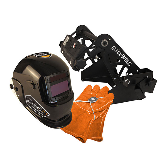
System Includes:
1.
Auto-darkening Welding Helmet with Guidance
Display and an SD card with 18 default Welding
Procedure Specifications (WPS's) in Helmet
2.
Angle Sensor (connected to Helmet)
3.
Stick Calibration Fixture
4.
Speed Shield with Brackets
5.
Screw knobs
6.
Speed Sensor with base
7.
Eight rechargeable batteries with battery charger
8.
Accessories/supplies: screwdriver, arm band, extra
protective speed lens, helmet protective shield, helmet manual
9.
Downloadable guideWELD® LIVE Curriculum
Additional Resources:
www.realityworks.com/guideweldlive-downloads
1.
User Guide
2.
guideWELD® LIVE Curriculum
3.
Available Standard WPS Lists and WPS Editor
4.
Product Support tutorials and documents
3
5
4
7
6
8
1
Advertisement
Table of Contents

Related Manuals for Realityworks guideWELD LIVE

Summary of Contents for Realityworks guideWELD LIVE
- Page 1 Eight rechargeable batteries with battery charger Accessories/supplies: screwdriver, arm band, extra protective speed lens, helmet protective shield, helmet manual Downloadable guideWELD® LIVE Curriculum Additional Resources: www.realityworks.com/guideweldlive-downloads User Guide guideWELD® LIVE Curriculum Available Standard WPS Lists and WPS Editor Product Support tutorials and documents...
- Page 2 ASSEMBLY INSTRUCTIONS Speed Sensor and Speed Shield Assembly Connect the Speed Sensor and Speed Shield to the base by attaching the two screw knobs. Both sides of each have pre-drilled holes. 1. Position threaded holes on the Speed Sensor (orange arrows) to the inside of the base arm (green arrows) 2.
-
Page 3: Speed Sensor
REFERENCE GUIDE TO SYSTEM PIECES Use the images below as you walk through the set-up of your guideWELD LIVE Helmet and the calibration process. Speed Sensor 1. On/off button (back of Speed Sensor) 2. Binding button (back of Speed Sensor) 3. - Page 4 HELMET SET-UP View Reference Guide to System Pieces 7. Choose Thickness. (page 3) for button positioning and Press the menu Helmet guides. select button to confirm 1. Turn on the Helmet and Speed Sensor 2. Look at the menu display, use naviga- tion buttons to determine a choice on each of the following screens 3.
-
Page 5: Calibration Process
CALIBRATION PROCESS NOTICE: The calibration process will need to be completed before each weld! The process includes Speed Sensor alignment and Angle Sensor calibration. The process is the same for Stick or MIG welding except when of using the Stick Calibration Fixture (for Stick welding only). Speed Sensor Alignment Joint/Coupon types Joint/Coupon Side Views... - Page 6 CALIBRATION PROCESS (continued) Angle Sensor Calibration During calibration process and during weld, maintain a firm grasp on welding gun and Angle Sensor. For best results, keep Angle Sensor in the same location (between palm of hand/glove and welding gun) without movement.* 1.
- Page 7 5. Grasp the welding gun in the desired holding position, pivot handle down and hold 6. Press and release the calibration button on the Speed Sensor. The calibrating screen will display in the Helmet. Wait for first part of the calibration to complete before continuing 7.
-
Page 8: Need More Help
Speed Sensor Batteries Additional Help and Information Notice: From the factory, the guideWELD LIVE Helmet and Speed Board are bound together. If using multiple units and/or Helmet and Speed Sensor combinations have changed, a binding process is necessary. Find process in Complete User Guide.
Need help?
Do you have a question about the guideWELD LIVE and is the answer not in the manual?
Questions and answers