Advertisement
Quick Links
Model:
MPPT12-2
Page 1 of 8
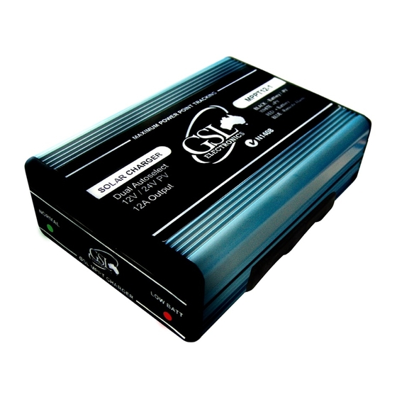
This revolutionary maximum power point tracker solar charger
was designed using the technology that won GSL Electronics the
prestigious "2008 EDN Innovation award". A simple, compact and
low cost alternative. Ideal for charging batteries with the new low
Efficiency Typical
Input Voltage
Output Voltage (Float)
Output Voltage (Bulk)
Output Power
Quiescent Current
Thermal Protection
Dimensions (mm)
Indications
Maximum Power Point Tracker
Please read these instructions before use
cost high efficiency grid type panels.
PATENT APPLIED FOR - 2010901565
MPPT12-2 Specifications
Flooded 14.5V / 29V, Sealed 14.2V / 28.4V
Peak 250W, constant 200W @29V / 150W @ 14.4V
Dual LED display – battery OK / LOW
Unit 2, 110 Station Road, Seven Hills ,NSW, 2147, Australia
200W Solar Charger
Operating Instructions
MPPT12-2 Unit
96%
16V to 55V
13.5V / 27V
0.04A
Multilevel type
35 X 75 X 100mm
MPPT12-2 R6
Advertisement

Summary of Contents for GSL MPPT12-2
- Page 1 Please read these instructions before use This revolutionary maximum power point tracker solar charger was designed using the technology that won GSL Electronics the prestigious “2008 EDN Innovation award”. A simple, compact and low cost alternative. Ideal for charging batteries with the new low cost high efficiency grid type panels.
- Page 2 • Before connecting battery always check battery and PV panel polarity. • When used with panels over 150W @ 12V or 200W @ 24V the MPPT12-2 MUST be fitted with the PVF fuse. Locate this fuse as close as possible to the MPPT. A 10A 60V fuse is recommended.
-
Page 3: Settings And Configurations
Please read these instructions before use Settings And Configurations: The MPPT12-2 factory default setting is for sealed lead acid batteries (Maximum charge voltage 14.2V and float voltage 13.4V) and auxiliary switch (grey wire) configured in Low Voltage Disconnect mode. The various operating modes can be configured with a combination of the green and yellow wires and the internal links CHE and REN. - Page 4 6 Hour DDS Set-Up (Sealed Battery) Grey 6 Hour DDS Set-Up (Vented Battery) All Night DDS Set-Up All Night DDS Set-Up (Sealed Battery) Grey All Night DDS Set-Up (Vented Battery) MPPT12-2 R6 Unit 2, 110 Station Road, Seven Hills ,NSW, 2147, Australia...
- Page 5 The LVD maximum load is 10A continuous and 20A for short transients below a few seconds. Grey Please ensure that your MPPT has been correctly configured (REN & CHE settings) for your application. Refer to the Settings and Configurations section for more information. MPPT12-2 R6 Unit 2, 110 Station Road, Seven Hills ,NSW, 2147, Australia...
- Page 6 Critical Load Please ensure that your MPPT has been correctly configured (REN & CHE settings) for your application. Refer to the Settings and Configurations section for more information. MPPT12-2 R6 Unit 2, 110 Station Road, Seven Hills ,NSW, 2147, Australia...
- Page 7 Grey LOAD Please ensure that your MPPT has been correctly configured (REN & CHE settings) for your application. Refer to the Settings and Configurations section for more information. MPPT12-2 R6 Unit 2, 110 Station Road, Seven Hills ,NSW, 2147, Australia...
- Page 8 Q: What are the GSL MPPTs advantages compared to standard solar regulators? 1. Suitable for new lower cost high efficiency grid type panels since the GSL MPPT can efficiently charge the batteries from relatively high voltage, say 12V batteries from 36V MPP panels.


Need help?
Do you have a question about the MPPT12-2 and is the answer not in the manual?
Questions and answers