Table of Contents
Advertisement
Quick Links
Advertisement
Table of Contents

Summary of Contents for ZepSolar Zep System I
- Page 1 VERSION 1.4...
- Page 2 ZEP SYSTEM I INSTALLATION MANUAL THIS MANUAL CONTAINS SAFETY, INSTALLATION, CONFIGURATION AND TROU- BLESHOOTING INSTRUCTIONS FOR ZEP SYSTEM I. ZEP SOLAR, INC. RECOM- MENDS THAT YOU SAVE THIS MANUAL IN A READILY ACCESSIBLE LOCATION SHOULD ANY QUESTIONS ARISE ABOUT THE ZEP SYSTEM.
-
Page 3: Table Of Contents
1.0 Getting Started - - - - - - - - - - - - - - - - - - - - - - 1 1.1 - Zep System I Overview - - - - - - - - - - - - - - - - - - - - - - - - - - - - - - 2 1.2 - Features &... - Page 4 5.2 - Servicing the Array - - - - - - - - - - - - - - - - - - - - - - - - - - - - - - - - 31 6.0 Zep System I Warranty - - - - - - - - - - - - - - - - - 37 6.1 - Limited Warranty - - - - - - - - - - - - - - - - - - - - - - - - - - - - - - - - - 38...
-
Page 5: Getting Started
ZEP SYSTEM I INSTALLATION MANUAL Getting Started Zep System I from Zep Solar, Inc. offers the fastest and least expensive way to mount rooftop PV arrays on tile roofs using a series of drop-in and quarter-turn connections to greatly acceler- ate the process. -
Page 6: Zep System I Overview
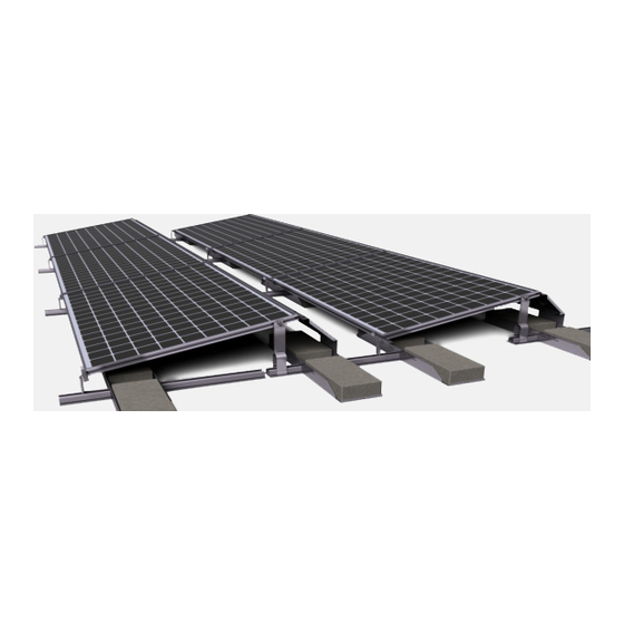
ZEP SYSTEM I INSTALLATION MANUAL 1.1 - Zep System I Overview The Zep System I from Zep Solar, Inc. is designed for use on sloped tile roofs. The mounting system preserves waterproofing by using tile hooks installed beneath the tiles and a reduced number of roof penetrations. -
Page 7: How It Works
It is important to understand the unique characteristics of Zep System I before installation in order to get the most from its unique capa- bilities. The key features that separate Zep System I and typical mounting systems are: •... - Page 8 ZEP SYSTEM I INSTALLATION MANUAL The Ground Zep rotates into the module groove with a quarter turn and provides a ground bond connection from the array to the equipment grounding conductor(s). Only one Ground Zep is required per sub-array and can be installed anywhere on the perimeter of the array.
- Page 9 ZEP SYSTEM I INSTALLATION MANUAL Zep System I is flexible in the X, Y, & Z axes, making square and level installations easy. The position and orientation of each module can be adjusted during installation, allowing the installer to keep the array aligned with system-level reference points such as a lower-edge chalk line and by sighting along seams and edges to make the array look good with little effort.
-
Page 10: Components
ZEP SYSTEM I INSTALLATION MANUAL 1.4 - Components Zep System I consists of the following components (PV modules not shown): Tile Hook (not included) Spanner Bar Spanner Clamp Cam Foot Hybrid Interlock Interlock Spanner Sleeve Array Skirt, Spacer, Jam Ground Zep & Wire Clip Copyright ©... -
Page 11: Additional Items
See Chapter 6 for instructions on using the Zep Tool and the Flat Tool. 1.6 - For Further Information Additional information about Zep System I is available online at Zep Tool www.zepsolar.com. The available resources include: Datasheet: The Zep System I datasheet contains technical details and •... - Page 12 ZEP SYSTEM I INSTALLATION MANUAL This page intentionally left blank. Copyright © 2012 Zep Solar, Inc. PAGE 8 OF 50...
-
Page 13: Safety Precautions
ZEP SYSTEM I INSTALLATION MANUAL Safety Precautions All instructions in this Installation Manual and all instructions in the installation manual provided by the PV module manufacturer must be read and understood before attempting to install Zep Sys- tem I. The installer assumes all risk of personal injury or property damage that might occur during the installation and handling of the components. -
Page 14: General Safety
Zep System is being installed can properly support the array under live load conditions. • The Zep System I must be installed over an appropriately rated fire resistant roof covering. • The Cam Feet and Interlocks must be fully engaged with both the PV modules and Spanner Bars. -
Page 15: System Design
ZEP SYSTEM I INSTALLATION MANUAL System Design Process Zep System I is designed for use on sloped tile roofs. This chapter provides a high-level overview of the process of assessing and planning a prospective Zep System I installation. Each installation is unique and has unique requirements that go beyond the high- level overview included in this manual. - Page 16 Bar E-W spacing, whichever value is lower. 3.3 - Getting Started Please contact Zep Solar, Inc. to begin planning your Zep System I installation if you have not done so a ready. You may contact Zep Solar, Inc. via: Email to sales@zepsola .com Phone to 1-415-32 -0768 Copyright ©...
-
Page 17: Installation
ZEP SYSTEM I INSTALLATION MANUAL Installation This chapter guides you through the Zep System I installation pro- cess. Please read this chapter in its entirety to familiarize yourself with the process before beginning the installation. You may also visit the Resources section at www.zepsolar.com to view videos and other training materials. -
Page 18: Step 1: Formulas & Layout Lines
ZEP SYSTEM I INSTALLATION MANUAL 4.1 - STEP 1: Formulas & Layout Lines To lay out a LANDSCAPE installation: E/W line spacing = per span tables. N/S line spacing = per span tables. Max cantilever is 1/3 of the distance between tile hooks. -
Page 19: Step 2: Install The Tile Hooks
ZEP SYSTEM I INSTALLATION MANUAL 4.2- STEP 2: Install the Tile Hooks 2-A: Lay out the locations of the tile hooks. NOTE: This manual details a landscape installation. Spanner Bars run parallel to rafters for landscape installations Spanner Bars run perpendicular to raf- ters for portrait installations. -
Page 20: Step 3: Installing Spanner Bars
ZEP SYSTEM I INSTALLATION MANUAL 2-D: Reinstall the tiles. Tiles may require grinding in order to fit flush. 4.3 - STEP 3: Installing Spanner Bars 3-A: Assemble the Spanner Bars. Slide Spanner Bar A onto the splice protruding from Spanner Bar B. - Page 21 ZEP SYSTEM I INSTALLATION MANUAL 3-C: Mount Spanner Bars to tile hooks. Use one 9/16” carriage bolt and flange nut per sleeve/tile hook. Tighten nut and bolt to snug tight. 3-D: Install the remaining Spanner Bars. Repeat Steps 3-A through 3-C for each remaining column (landscape) or row (portrait) of Spanner Bars.
- Page 22 ZEP SYSTEM I INSTALLATION MANUAL 3-F: Secure the Cam Foot using the Flat Tool. Use Flat Tool to tighten Cam Foot 1/4 turn clockwise as shown. Ensure Cam Foot is oriented with the Tongue side up as shown in Image 2.
-
Page 23: Step 4: Installing The Array Skirt
ZEP SYSTEM I INSTALLATION MANUAL 4.4 - STEP 4: Installing the Array Skirt 4-A: Place a Array Skirt Spacer over an Interlock This is necessary for the Interlock to properly engage the Array Skirt. NOTE: Array Skirt Spacers are only needed for Interlocks that connect to the Array Skirt. - Page 24 ZEP SYSTEM I INSTALLATION MANUAL 4-D: Place the Array Skirt onto the Cam Feet. The Key side of the Cam Feet must engage with the groove in the Array Skirt. If using a Hybrid Interlock, align the Array Skirt with the center mark. (See Section 5.1)
-
Page 25: Step 5: Installing The First Module
ZEP SYSTEM I INSTALLATION MANUAL 4.5 - STEP 5: Installing the First Module 5-A: Lower module onto Cam Feet. The module groove rests on the Tongue side of Cam Feet and Inter- locks. 5-B: Verify module alignment. The Array Skirt should extend approxi- mately 1/4”... - Page 26 ZEP SYSTEM I INSTALLATION MANUAL 5-D: “Drop in” module onto front Cam Feet and Interlocks. Press the module forward while lower- ing it to the plane of the roof (0 degrees) to fully engage the Cam Foot. If the module does not fully seat, raise it slightly (4-5 degrees) and press for- ward again while lowering.
-
Page 27: Step 6: Installing The Remaining First-Row Modules
ZEP SYSTEM I INSTALLATION MANUAL 4.6 - STEP 6: Installing the Remaining First-Row Modules 6-A: Place module on front row Cam Feet. Repeat Steps 5-A through 5-D for the next module. This module should be approx. 1/2” distant from the first module. -
Page 28: Step 7: Finishing The First Row
ZEP SYSTEM I INSTALLATION MANUAL 6-D: Add rear Cam Foot. Attach and secure as described in Step 5-E. 4.7 - STEP 7: Finishing the First Row 7-A: Add the remaining modules to the first row. Repeat Steps 6-A through 6-D for each remaining module in the row. -
Page 29: Step 8: Installing The Next Rows
ZEP SYSTEM I INSTALLATION MANUAL 4.8 - STEP 8: Installing the Next Rows 8-A: Add the remaining rows of modules. Repeat Steps 5 through 7 for the remaining rows of modules. Adjust module truing (X-Y axes) and leveling (Z axis) as you go as described in Step 8-B for a square, level array. -
Page 30: Step 9: Grounding
ZEP SYSTEM I INSTALLATION MANUAL 4.9 - STEP 9: Grounding 9-A: Insert a Ground Zep into the module. Grounding as soon as the first module is installed ensures that the array is grounded during installation for tech- nician safety. Insert the Ground Zep into the module groove with the set screw at the 9 o’clock position. -
Page 31: Step 10: Wire Clips
ZEP SYSTEM I INSTALLATION MANUAL 4.10 - STEP 10: Wire Clips 10-A: Place the Wire Clip in the module groove. Set the Wire Clip in the module groove. Ensure that the Wire Clip is sitting flush with the bottom of the module groove. - Page 32 ZEP SYSTEM I INSTALLATION MANUAL This page intentionally left blank. Copyright © 2012 Zep Solar, Inc. PAGE 28 OF 50...
-
Page 33: Options & Servicing
Options & Servicing This chapter describes the standard and Hybrid Interlocks used for the Zep System I. Most modules will connect to Spanner Bars using standard Cam Feet; however, Hybrid Interlocks may be used in certain cases. This chapter also describes the process of remov- ing a module for servicing or replacement. -
Page 34: Interlock Vs. Hybrid Interlock
ZEP SYSTEM I INSTALLATION MANUAL 5.1 - Interlock vs. Hybrid Interlock Zep System I uses two types of Interlock: standard and hybrid. Option A: Standard Cam Foot and Interlock. The standard Cam Foot (A) secures a module to the Spanner Bar anywhere along the module frame. -
Page 35: Servicing The Array
ZEP SYSTEM I INSTALLATION MANUAL 5.2 - Servicing the Array Remove modules by column to access a faulty module. See Chapter 6 for tool use instructions. SVC-A: Start at the top of the column with the faulty module. Work from the top down, removing one module at a time. - Page 36 ZEP SYSTEM I INSTALLATION MANUAL SVC-D: Remove the first module. Pull module back and rotate up 15 15° degrees, then rotate module up and out of the array. SVC-E: Remove Interlock(s) from the next row of modules. Rotate both fasteners to Position #1 using Flat Tool as shown.
- Page 37 ZEP SYSTEM I INSTALLATION MANUAL SVC-G: Remove the next module. Remove the Cam Foot. Rotate the module up and out of the array. SVC-H: Remove the remaining modules. Repeat Steps SVC-E through SVC-G to remove the remaining modules until you reach the module you are going to replace.
- Page 38 ZEP SYSTEM I INSTALLATION MANUAL SVC-J: Position the Interlock(s). Slide the Interlock into position. Twist the Interlock with the Flat Tool to press the lugs back into the groove in the module. SVC-K: Secure the Interlock(s) Twist the fasteners to Position #3 using the Flat Tool.
- Page 39 ZEP SYSTEM I INSTALLATION MANUAL SVC-M: Install the remaining modules. Follow Steps SVC-H through SVC-L to install the remaining modules in the column. Copyright © 2012 Zep Solar, Inc. PAGE 35 OF 50...
- Page 40 ZEP SYSTEM I INSTALLATION MANUAL This page intentionally left blank. Copyright © 2012 Zep Solar, Inc. PAGE 36 OF 50...
-
Page 41: Zep System I Warranty
ZEP SYSTEM I INSTALLATION MANUAL Using the Zep and Flat Tools This chapter describes the Zep Tool and the Flat Tool used for installing and maintaining Zep System arrays. Each tool has sev- eral uses and is designed to make working with Zep components fast and easy. - Page 42 ZEP SYSTEM I INSTALLATION MANUAL 6.1 - The Zep Tool The Zep Tool appears as shown here. Installing Interlocks interlocks install at Position #1. Insert the Interlocks in the PV module groove as described in the installation instructions. Place the Zep Tool over the fastener with the 1 aligned with the reference mark on the Interlock.
- Page 43 ZEP SYSTEM I INSTALLATION MANUAL Interlocks can be used for thermal joints at Position #2. If your array requires thermal expan- sion joints (refer to the installation instructions and site design docu- ments), the Interlocks forming the joint secure at Position #2.
- Page 44 ZEP SYSTEM I INSTALLATION MANUAL Leveling Cam Feet Level Cam Feet with a #30 Torx bit inserted into the Zep Tool. Insert the #30 Torx bit into the handle end of the Zep Tool. Engage the Torx bit with the adjust- ment screw inside the Cam Foot.
- Page 45 ZEP SYSTEM I INSTALLATION MANUAL Ground Zeps Engage Zep Tool with Ground Zep and rotate to lock into place. Press the Ground Zep into the module groove at the desired location. Engage the Zep tool with the Ground Zep. Rotate 90 degrees CW to lock the Ground Zep into place.
- Page 46 ZEP SYSTEM I INSTALLATION MANUAL 6.2 - The Flat Tool The Flat Tool appears as shown here. Installing Interlocks Engage the fastener at Position #1. Hook the end of the Flat Tool on the Interlock fastener at Position 1, as shown.
- Page 47 ZEP SYSTEM I INSTALLATION MANUAL Interlocks can be used for thermal joints at Position #2. If your array requires thermal expan- sion joints (refer to the installation instructions and site design docu- ments), the Interlocks forming the joint secure at Position #2.
- Page 48 ZEP SYSTEM I INSTALLATION MANUAL tap to the side. fastener drops from groove, slide other way to complete removal if needed. Installing Cam Feet in Modules You may use the Flat Tool to install Cam Feet in Modules. Hook the Rock In portion of the Flat Tool onto the Cam Foot as shown.
- Page 49 ZEP SYSTEM I INSTALLATION MANUAL Installing Cam Feet in Spanner Bars Rotate the Cam Foot into place in the module groove. Rotate the Cam Foot into place in the module groove using the Rock In por- tion of the Flat Tool as shown.
- Page 50 ZEP SYSTEM I INSTALLATION MANUAL This page intentionally left blank. Copyright © 2012 Zep Solar, Inc. PAGE 46 OF 50...
- Page 51 ZEP SYSTEM I INSTALLATION MANUAL Zep System I Warranty This chapter contains the Zep System I limited warranty. Please visit www.zepsolar.com for additional resources including product support, training, and service needs. Zep Solar, Inc. is always add- ing additional information to the site in response to customer needs.
-
Page 52: Limited Warranty
ZEP SYSTEM I INSTALLATION MANUAL 7.1 - Limited Warranty What is Covered Zep SOLAR, INC., a California corporation, (called “Zep Solar”) with its principal place of busi- ness located at 161 Mitchell Blvd., Suite 104, San Rafael, California 94903 warrants to the origi- nal retail purchaser (called “Purchaser”) of Zep Solar’s solar module rack products,... - Page 53 ZEP SYSTEM I INSTALLATION MANUAL they were not designed, or if the Products have been modified, repaired, or reworked in a manner not previously authorized by Zep Solar in writing. Zep Solar’s Warranty covers only the Products and components provided by Zep Solar. Zep Solar makes no warranties or representations regarding any items or material provided by third par- ties.
- Page 54 ZEP SYSTEM I INSTALLATION MANUAL This page intentionally left blank. Copyright © 2012 Zep Solar, Inc. PAGE 50 OF 50...
- Page 55 ZEP SYSTEM I INSTALLATION MANUAL This page intentionally left blank. Copyright © 2011 Zep Solar, Inc.
- Page 56 Zep System I Installation Manual VERSION 1.2 © Copyright 2012 Zep Solar, Inc. For product and purchase inquiries contact: www.ecodirect.com | 888-899-3509...
Need help?
Do you have a question about the Zep System I and is the answer not in the manual?
Questions and answers