
Subscribe to Our Youtube Channel
Related Manuals for BERG DCi


Summary of Contents for BERG DCi
- Page 1 Product manual for the BERG DCi - Meter Installation I Device description I Operation Edition: 28.01.2008...
- Page 2 BERG. All of the trademarks named in this manual are the property of BERG or the respective title holders. BERG Energiekontrollsysteme GmbH is certified accord. to DIN ISO 9001:2000 and continually endeavors to improve their products.
-
Page 3: Table Of Contents
Contents page Prologue....................... 5 Safety tips ......................5 Maintenance and guarantee tips ................5 Mounting and installation ................... 6 Mounting the meter ....................6 Installation ......................7 2.2.1 Connection examples.................... 8 General description................... 10 Standards and regulations ................11 Housing-, operation and display elements ............. 12 Overview ...................... - Page 4 Figure index Figure 1: Dimensions (direct connected meter) .............. 6 Figure 2: Housing-, operation and display elements............. 12 Figure 3: Layout of the display..................13 Figure 4: Function circuit diagram (direct connected meter) ......... 15 Figure 5: Function circuit diagram (transformer operated meter)........15 Figure 6: System layout - RS485-two wire bus .............
-
Page 5: Prologue
1 Prologue This manual describes all designs of the DIZ meter (firmware version 3.03 and higher). Please note that the meters can be designed differently regarding, for example, configuration, interfaces in-/outputs etc. It is therefore possible that meter features are described here which do not apply to the meter(s) used by you. -
Page 6: Mounting And Installation
2 Mounting and installation 2.1 Mounting the meter Meters from the series DIZ are designed for mounting on DIN-rails TH 35-7.5 accord. to DIN 60715. Figure 1: Dimensions (direct connected meter) -
Page 7: Installation
2.2 Installation When installing the meter, please pay careful attention to the connection diagram which can be found on the inside the terminal cover. On page 8 you can find examples of connection diagrams. The direct connected version from the series DIZ can be connected to a 3- or 4-phase busbar with a left-sided N-connection. -
Page 8: Connection Examples
Current terminals / Voltage Auxiliary N-terminal terminals terminals up to 65 A up to 5 A up to 65 A up to 5 A up to 65 A up to 5 A Terminal dimensions 6.9 x 7.9 3.3 x 3.0 2.7 x 3.0 2.7 x 3.0 d = 2.5... - Page 9 4-wire version, connected to a current transformer ES: Control input (system voltage) 4-wire version, direct connection ES: Control input (system voltage) 4-wire version, connected to current and voltage transformer ES: Control input (system voltage) 4-wire version, connected to current – and voltage transformers (3 voltage transformers) (auxiliary circuit with 2 current transformers) ES: Control input (system voltage) 4-wire version, connected to current- and voltage transformers...
-
Page 10: General Description
3 General description The DIZ meter is a digital 1- or 2- tariff meter for measuring positive- and negative active energy in 2-, 3- and 4-wire networks. Tariff switching takes place via an external control input. DIZ meters are principally used for energy data registration in the industry and building installation, switching stations and the field of energy supply. -
Page 11: Standards And Regulations
4 Standards and regulations DIN EN 14908-1, -2 Open Data Communication in Building Automation, Controls -3, -4 and Building Management - Building Network Protocol DIN EN 13757-2, -3 Communication systems for meters and remote reading of meters EN 50470-1 Electricity metering equipment (a.c.) - Part 1: General requirements, tests and test conditions - Metering equipment (class indexes A, B and C) EN 50470-3... -
Page 12: Housing-, Operation And Display Elements
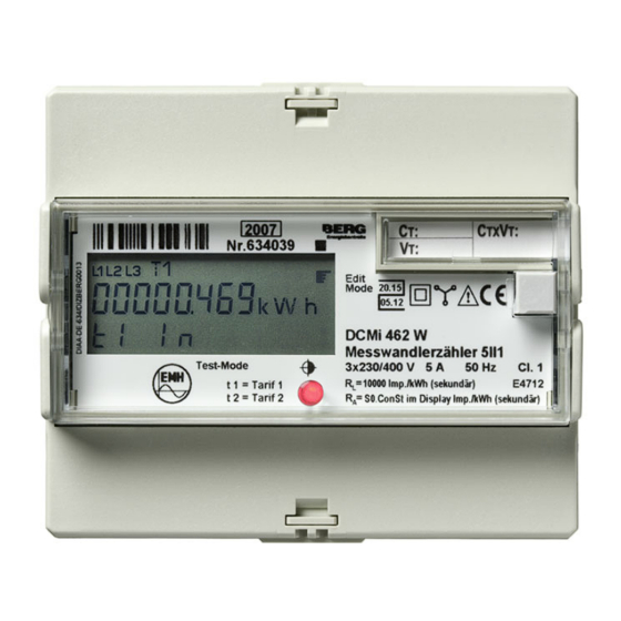
5 Housing-, operation and display elements 5.1 Overview 5 6 7 9 10 16 17 Figure 2: Housing-, operation and display elements Description Foldaway terminal cover LC-Display Seal eye Neuron-ID-number (meters with LON-interface only) Protection class II Type of network and load Pay attention to package insert Non-reverse ratchet or bidirectional meter ( EC type-examination certificate... -
Page 13: Display
5.2 Display The DIZ meter has a liquid crystal display (LCD) with the following layout. Figure 3: Layout of the display Description Phase display L1, L2, L3 are continually lit up: Phase voltages are applied. L1, L2, L3 flash: Phase sequence of the voltage is wrong Display of active tariffs Tariff 1 is active Tariff 2 is active... -
Page 14: Technical Description
6 Technical description 6.1 Technical data Transformer operated meter Direct connected meter 5II1 A / 5 + 1 A and 1 A 5(65) A / 0.25 – 5(65) A 3x230/400 V, 3x290/500 V, 4-wire meter 3x230/400 V, 3x290/500 V Voltage 3x58/100 V, 3x63/110 V 3x100 V, 3x110 V, 3-wire meter... -
Page 15: Function Circuit Diagrams
6.2 Function circuit diagrams 6.2.1 Direct connected meter up to 65 A Figure 4: Function circuit diagram (direct connected meter) 6.2.2 Transformer operated meter up to 5 A Figure 5: Function circuit diagram (transformer operated meter) -
Page 16: Inputs
6.3 Inputs In the two tariff version the DIZ meter has a control input (system voltage) for tariff switching. Specifications System voltage 58...230 V AC (standard) Table 5: Specifications of the inputs 6.4 Outputs The DIZ has a potential free S0-output (accord. to DIN 43 864) or a potential free MOSFET-output (semi-conductor relay). -
Page 17: Impulse-Led
6.4.3 Impulse-LED If transformer ratios are set, they do not have any effect on the Impulse-LED. The LED constant (R ) depends on the version and is always based on secondary values. 6.5 Interfaces 6.5.1 M-Bus-interface The M-Bus interface is designed accord. to DIN EN 13757-2, -3. Via M-Bus the following parameters can be transmitted: −... -
Page 18: Rs485-Interface
6.5.3 RS485-interface The electrical interface RS485 is a symmetrical two wire interface (half duplex) and is designed in accordance with TIA/EIA-485 / ITU-T V.11. The data protocol is the M-Bus protocol. The following parameters can be transferred via the RS485 interface: - Manufacturer identification, as an option freely selectable - Medium - Primary- and secondary addresses M-Bus... -
Page 19: Battery
6.6 Battery As an option, the DIZ meter can be equipped with an internal battery which allows a readout of the meter when it is switched off. As long as the meter operates continuously via the battery, the lifetime of the battery is at least 30 hours. With a de-energised read out once a month (approx. -
Page 20: Operation Of The Meter
7 Operation of the meter The DIZ meter is operated via a mechanical button. With this button the display is controlled and settings in the edit mode can be carried out. If the meter is equipped with a battery, the standard menu can be shown in the display when the meter is switched off. However, the test mode, address menu (with meters with electrical interface) and edit menu are not available in this condition. -
Page 21: Standard Menu
7.1.1 Standard menu In the normal operation mode the meter is in the standard menu. In the display the energy value of the active tariff is displayed. To switch to the next menu option, press the button - short. At the end of the standard menu there is the possibility to change over to the test mode, address menu or to the edit mode , press the button - long. - Page 22 continuation of the standard menu U-Transformer constant (only with transformer meters) I-Transformer constant (only with transformer meters) Power P for all phases Power P for phase 1 With a negative performance display, the current transformer connection L1 (terminals 1-3) must be checked. Power P for phase 2 With a negative performance display,...
- Page 23 continuation of the standard menu Current I phase 3 Output constant in Imp./kWh (only with meters with pulse output) Pulse length in seconds (only with meters with pulse output) Primary address (only with meters with M-Bus/RS485-interface) Secondary address (only with meters with M-Bus/RS485-interface) Baud rate M-Bus (only with meters with...
-
Page 24: Test Mode (For Certification Only)
7.1.2 Test mode (for certification only) A flashing star in the display shows that the meter is in the test mode. In the standard display of the test mode both tariff registers (T1 and T2) of the momentary active energy direction or the last active energy direction are always displayed (if configured). - Page 25 continuation of the test mode Tariff 1, negative active energy (if configured) Tariff 2, negative active energy (if configured) U-Transformer constant (only with transformer meters) I-Transformer constant (only with transformer meters) Output constant in Imp./kWh (only with meters with pulse output) Pulse length in seconds (only with meters with pulse output)
-
Page 26: Address Menu
continuation of the test mode Activation of the To the next address menu menu option Entry into the address menu (see chapter 7.1.3 Address menu) Activation of the To the edit mode standard display Entry into the edit mode (see chapter 7.1.4 Edit mode) Table 10: Test mode 7.1.3 Address menu... - Page 27 Edit example: In the following table the value for the primary address is changed from 001 to 002. To change the secondary address and the baud rate the following method should be used. Address menu Menu option Display Button (operation leads to the next menu option if not specified differently) Activation of the...
-
Page 28: Edit Menu
7.1.4 Edit menu The edit mode is only available for uncertified meters. After certification of the meter the values in the edit mode cannot be changed. The status of the edit menu is shown by a hand symbol in the display: flashing hand symbol: Edit mode is active, the edit data can be changed continually lit up hand symbol: Edit mode is deactivated, it can however be activated with a configured password function by means of a password... - Page 29 e) Pulse duration The pulse time can be set in to 30 ms, 50 ms or 100 ms depending on the pulse value. − 30 ms (f = 16.7 Hz) − 50 ms (f = 10 Hz) − 100 ms (f = 5 Hz) With a primary pulse output, the pulse value and the pulse duration cannot be changed.
- Page 30 Note: If the button is not operated for longer than 5 minutes, the display returns to the standard display. Thereby the edit mode is not locked which means the data can be edited again later. = short pressing of the button (t <...
- Page 31 continuation of the edit mode I-Transformer constant To the next (only with transformer meters) menu option Edit value Example: Changing the register digitness Display digitness of To the next the energy register menu option Edit value Set value Next value (value flashes) Take over value New set value...
- Page 32 continuation of the edit mode Leave test mode and To the next change to standard mode menu option (only with an activated test mode) Edit value Leave edit mode To start of the menu Edit value “ESCAPE” flashes To the display “CLOSE”...
-
Page 33: Appendix
D-82152 Martinsried certifies that the following products Product designation: Electricity meter DCi are in conformity with the specification of the EC Directive 93/68/EC. Statement relating to EMC Directive (89/336/EC) The electricity meter conform to the requirements of the EC Directive „Electromagnetic compatibility“ 89/336/EC, including those specified in standards EN 5502 2 +A1 +A2 and EN 61000-4-2, -3, - 4, -5, -6, -12. -
Page 34: Declaration Of Conformity To Ec Type-Examination Certificate
D-82152 Martinsried certifies that the following products Product designation: electricity meter DCi corresponds the EC type-examination certificate DE-07-MI003-PTB011. Statement relating to Directive 2004/22/EC The electricity meter conform to the requirements of the Directive 2004/22/EC of the European Parliament and of the Council of 31 March 2004 on measuring instruments (OJ L 135 p.
Need help?
Do you have a question about the DCi and is the answer not in the manual?
Questions and answers