Advertisement
Quick Links
Advertisement

Subscribe to Our Youtube Channel
Summary of Contents for api technologies corp. SmartStep 150T
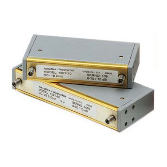
- Page 1 IM-275 INSTALLATION & OPERATING INSTRUCTIONS Models 150T, 151T, & 152T ® SmartStep Programmable Attenuators This documentation may not be reproduced in any form, for any purpose unless authorized in writing by API / Weinschel, Inc. © API / Weinschel, Inc. Frederick, Maryland 1997 - 2015 REV.
- Page 2 IM-275 GENERAL This manual provides general installation instructions and wiring data to be used as an aid in installing the API /Weinschel Model 150T, 151T and 152T Series SmartStep Programmable Attenuators into any subsystem or applica- tion. Also included are specifications and other technical data to help in the installation and operation of your 150T Series Programmable Attenuator.
-
Page 3: Cell Configuration
150 T Series SmartStep ® Programmable Attenuators BUILT-IN SMARTSTEP DRIVER CIRCUITRY: These SmartStep ® attenuators feature an internal microcontroller-based driver that provides a TTL-level digital interface for control of the attenuator relays. This card simplifies operation and interfacing requirements, while at the same time providing for greatly enhanced flexibility over past designs. User-selectable modes of operation include both parallel and serial Smartstep bus. -
Page 4: Installation
IM-275 INSTALLATION MOUNTING: Each Programmable Step Attenuator is supplied with two mounting screws (P/N MS35335-57). These screws will fit any of the mounting holes (4-40 UNC-2B x 0.22 MIN DP) located on either side of the attenuator. RF CABLE INSTALLATION: Care should be taken to prevent strain on the inter- connecting cables, since damage here may not always be apparent. - Page 5 150T Series SmartStep ® Programmable Attenuators PARALLEL MODE OPERATION: In the parallel mode of operation, the Smartstep attenuator accepts TTL-level parallel data on the D0-D7 input data lines. Each data line controls a separate attenuation cell, where a logic 1 input (TTL high) engages the attenuation cell, and a logic 0 input (TTL low) bypasses the cell, providing a through path.
-
Page 6: Specifications
IM-275 SPECIFICATIONS NOMINAL IMPEDANCE: 50 Ω FREQUENCY RANGE: Model 151T: dc to 4 GHz Model 150T: dc to 18 GHz Model 152T: dc to 26.5 GHz DRIVER INTERFACE: Input Supply Voltage: +12.0 to +15.0V Control Signals: TTL/CMOS compatible Interface Modes: parallel/ I C serial DC Characteristics (at 25 °C):... - Page 7 150T Series SmartStep ® Programmable Attenuators MAXIMUM SWR (50 Ω Characteristic Impedance): Frequency (GHz) APPLICABLE MODELS dc-4 4-18 18-26.5 151T-11, 151T-15, 151T-62, 1.50 - - - - - - 151T-75, 151T-110 150T-11, 150T-15, 150T-62, 1.50 1.90 - - - 150T-75, 150T-110 151T-70 (3 cell) 1.35 - - -...
- Page 8 IM-275 Specification (con’t): Model 150T/151T/152T-11 & 150T/151T/152T-15: Frequency Attenuation Setting (dB) Range (GHz) dc-4 0.2 0.2 0.3 0.3 0.3 0.3 0.4 0.4 0.4 0.4 0.5 0.5 0.5 4-12.4 0.3 0.3 0.4 0.4 0.5 0.5 0.6 0.6 0.6 0.6 0.7 0.7 0.7 12.4-18 0.5 0.6 0.6 0.6 0.6 0.7...
-
Page 9: Physical Dimensions
150T Series SmartStep ® Programmable Attenuators PHYSICAL DIMENSIONS: 3 cell 83.0 (3.27) 76.2 (3.0) 101.6 (4.00) 4 cell 110.7 (4.36) 103.6 (4.06) 129.2 (5.09) 5 cell 136.9 (5.39) 129.8 (5.11) 156.2 (6.15) NOTE: All dimensions are given in mm (inches) and are maximum, unless otherwise specified. CONTACTING API / Weinschel In the event you're having difficulty or believe that the components are defective, please contact Weinschel immediately. - Page 10 IM-275 ACCESSORIES Model 8210 Smartstep Interface: The Model 8210 Smartstep Interface provides a flexi- ble, low cost solution for the operation of programmable step attenuators and other electromechanical devices under computer control. Designed to interface to Weinschel's new line of Smartstep Programmable Attenuators, the 8210 represents a new concept in device control applications for bench test and subsystem designs.
- Page 11 ® 150T Series SmartStep Programmable Attenuators Other 150T SmartStep Programmable... Frequency Attenuator Range/Step Size Range (GHz) Cells 11/1 dB 15/1 dB 55/5 dB 62/2 dB 70/10 dB 75/5 dB 90/10 dB 110/10 dB dc-4 GHz 151T-11 151T-15 151T-75 151T-110 151T-70 151T-62 dc-18 GHz 150T-11...
- Page 12 5305 Spectrum Drive, Frederick, Maryland 21703-7362 TEL: (301) 846-9222, 800-638-2048, FAX: (301) 846-9116 Web: www.weinschel.apitech.com, e-mail: weinschel-sales@apitech.com © 1997-2015, API / Weinschel, Inc.
Need help?
Do you have a question about the SmartStep 150T and is the answer not in the manual?
Questions and answers