Advertisement
Quick Links
Features
• 3-CCD Prismatic Color Linescan Camera
• High Sensitivity and High SNR Performance Linear CCD Sensors
• 1024 Pixels 10 x 10 µm or 14 x 14 µm
• 2048 Pixels 10 x 10 µm
• Excellent CCD Alignment Accuracy
®
• CameraLink
Format Data Rate: 20, 25, 33, up to 40 Mpixels/s
• Dynamic Range: 12-bit Channel
• Single Power Supply: 20 to 36 V
• Flat Field Correction Included
• Easy Camera Control with Programmable Settings
• Memory for Storing up to 60 Configurations
• High Reliability - CE and FCC Compliant
Description
™
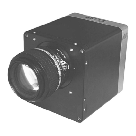
The AKYLA
is a rugged, high-performance, fully digital color linescan camera for
demanding industrial applications. It consists of a high-accuracy 3-CCD architecture
with a choice of either 1024 or 2048 pixel sensors at speeds up to 40 million pixels per
second and per color channel. The AKYLA cameras are optimized for high sensitivity
and precise color recognition.
Applications
• Web Inspection
• Inspection of Natural Materials like Food, Wood, Ore, Minerals and Lumber
• Recycling
• Quality Control in Printing Processes
• Texture Recognition
DC
®
CameraLink
3-CCD Color
Linescan
Camera
™
AKYLA
HD 20/25/33/40
1010/1014/2010 CL
Advertisement

Related Manuals for Atmel AKYLA HD 20 CL

Summary of Contents for Atmel AKYLA HD 20 CL
- Page 1 Features • 3-CCD Prismatic Color Linescan Camera • High Sensitivity and High SNR Performance Linear CCD Sensors • 1024 Pixels 10 x 10 µm or 14 x 14 µm • 2048 Pixels 10 x 10 µm • Excellent CCD Alignment Accuracy ®...
- Page 2 Keep the shade cap on the camera head when it is not in use to avoid contaminating the prism. If the front surface of the prism is very dirty, we recommend the camera be serviced by Atmel, since the surface area of the prism cannot be fully accessed from the front.
- Page 3 AKYLA HD 20/25/33/40 CL Transportation Transport the camera in its original packaging. If the original packaging has been discarded, package the camera with care in a thick layer of soft, preferably anti-static material. Do not use 2. Camera Characteristics Overview Table 2-1.
- Page 4 3. Technical Specifications Table 3-1. Technical Specifications of the AKYLA HD Series of Cameras with 10 µm Sensors Parameter Symbol Typical Unit Notes 1024 Number of pixels – – – – 2048 Pixel size – – 10 x 10 – µm 100% fill factor Data rate per CCD...
- Page 5 • Shielded power supply cable • CameraLink data transfer cable ref. 14B26-SZLB-500-OLC (3M) • Linear AC-DC power supply Atmel recommends using the same configuration to ensure compliance with the following standards. European AKYLA cameras comply with the requirements of the European directive 89/336/EEC, EMC (Electromagnetic Compatibility) .
- Page 6 Figure 5-1. RGB Color Separation Beam Splitter Green Blue Incoming Light The CCDs are aligned to obtain a perfect image of the three measured color components. All three CCDs see exactly the same area of the object at the same time. The corresponding pix- els of all three sensors are optically positioned in the same place (Figure 5-2).
- Page 7 AKYLA HD 20/25/33/40 CL Figure 6-1 shows the prism’s reaction at each wavelength. Transmissivity is well balanced, both in the sense of peak response and the total amount of light passed to the sensors at each wavelength (sum of the three separate curves). This all results in excellent color separation compared to tri-linear CCD sensors.
- Page 8 Figure 6-3. Camera Synoptic Data Out 12-bit Non Volatile Memory 12-bit Voltage 12-bit Monitoring Temperature CTRL Monitoring 12-bit Ctrl Out 12-bit Ctrl In 12-bit RS-232 Timing Gain Ctrl The AKYLA HD cameras operate in a monoshot mode. For each rising edge of the NewLine signal, the camera responds by sending out the digital data stream of the previous linescan time period.
- Page 9 AKYLA HD 20/25/33/40 CL 7. Timing Figure 7-1. Relationship Between the Data Output and NewLine (CC1) Signals Line Scan Period Line 1 Line 2 Line 3 NewLine (CC1) Data Out Line 0 Line 1 Line 2 Line 3 The effective integration time can be made shorter than the actual linescan period (time between two consequent NewLine pulses) by holding the ExpCtrl (CC2) signal in its active state until the beginning of the targeted interception period.
- Page 10 Timing Diagrams Figure 7-3. Parallel Color Channel Mode, 20/25 MHz per Channel NewLine Input Change of Line Internal ExpCtrl Input Line Valid Output Pixel Strobe Output Data 29-0 N = 1024 Figure 7-4. Timing Diagram Pixel Strobe Data 29-0 i - 2 i - 1 AKYLA HD 20/25/33/40 CL 5335C–IMAGE–06/05...
- Page 11 AKYLA HD 20/25/33/40 CL Table 7-1. Timings Symbol Parameter Unit NewLine low 0.05 – µs Linescan period AKYLA HD20 1010/1014 55.7 – – µs AKYLA HD25 1010/1014 44.7 – – µs AKYLA HD33 1010/1014 33.7 – – µs AKYLA HD40 1010/1014 28.2 –...
- Page 12 8. Processing of CCD Output Analog Video Path Atmel AKYLA HD cameras use a two-channel Atmel CCD for each color. Figure 8-1 is a sim- plified illustration of the analog video path of one channel. The video path itself is completely analog until digitized with a 12-bit resolution in close vicinity of the CCD itself.
- Page 13 Pixel Correction Unit 8.2.1 Description The Atmel AKYLA HD series line scan cameras incorporate a user-programmable real-time pixel correction unit, PCU. The PCU can be set-up by downloading the appropriate correction data via the RS-232. The PCU can simultaneously perform white balancing, removal of pixel to pixel offsets (PRNU and DSNU), lighting profile correction, removal of lens curvature and/or perform custom oper- ations on the camera’s output data.
- Page 14 Within a single color pixel the data is ordered into a multiplier and an offset. The multiplier con- sists of 14 bits and the offset of 10 bits. Thus, the three bytes that make up the correction data for one color pixel are internally divided on a bitwise level, as shown in Table 8-1: Table 8-1.
- Page 15 AKYLA HD 20/25/33/40 CL The multiplier a has a 14-bit range. The multiplier is scaled so that a 14-bit multiplier value of 4096 DU by default equals multiplying by 1. Therefore, to increase the signal of a pixel it has to be multiplied with a number greater than 4096 DU and accordingly, has to be multiplied with a smaller number to attenuate the signal.
- Page 16 8.2.4.1 Example on Performing Multiple Corrections White balancing can be achieved by selecting multipliers so that the data values on all color channels have an equal digital response from pixel to pixel. Normally, the channel that is clos- est to saturation is selected as a reference for the other channels. Other choices are possible but they limit the dynamic range of the output signal.
- Page 17 AKYLA HD 20/25/33/40 CL 9. Electrical Interface All the electrical connections of the AKYLA color linescan camera are made via the rear panel. The DC power is input via the 2-wire shielded power cable (included in the delivery). The two CameraLink connectors are used for interfacing with commercial CameraLink frame grabber boards or your own electronic equipment.
- Page 18 Table 9-1. LED Indicator Description LED Indicator Color Description On: camera is ready for operation with correction data loaded STATUS 2 Green Off: camera is performing internal boot cycle PWR ERR On: at least one of the internal supply voltages has failed On: warning that the internal temperature is too high.
- Page 19 AKYLA HD 20/25/33/40 CL Table 9-3. Power Supply Connector Pinout Signal Signal Figure 9-3. Receptacle Viewed from Behind the Camera The AKYLA cameras operate from a single supply voltage of nominally 24 V at typically 500 to 1000 mA, depending on the mode of operation and the external terminations of the output signals.
- Page 20 All the input signals are internally terminated by 100 Ω resistors. All the output signals should be terminated respectively (one 100 Ω resistor connected between the positive and negative wire of each signal pair). Table 9-4. CameraLink Output Bits Port Assignments Multiplexed Parallel All Modes...
- Page 21 AKYLA HD 20/25/33/40 CL Table 9-4. CameraLink Output Bits Port Assignments (Continued) Multiplexed Parallel All Modes Base Dual Base Medium 24-bit + 8-bit 10-bit 12-bit 24-bit 30-bit 36-bit 30-bit 36-bit Note: The grey boxes show the bits that are not intended to be used, but which are present because of the camera’s hardware wiring (copies of output pins).
- Page 22 10. Mechanical Structure 10.1 Mechanical Dimensions and Mounting of the Camera The camera’s mechanical structure is compact and meets the rigid demands of the industrial environment. The aluminium camera case provides excellent electrical protection against external electromagnetic interference. When selecting the components, corrosion resistant properties were also considered.
- Page 23 11.2 Description The Atmel AKYLA HD series linescan cameras have user-programmable features that are available with either the RS-232 or the CameraLink port and a simple protocol. If your camera does not support all of these features or if you are not sure which functions are included, con- tact Atmel for details and upgrades (hotline-cam@gfo.atmel.com).
- Page 24 The values of these registers form a memory bank that can be saved into one of the internal non-volatile memory banks for future reloading. All the registers are automatically set to the values of memory bank 0 on power-up (see ”Memory Functions (Addresses 190 and 191)”...
- Page 25 AKYLA HD 20/25/33/40 CL 11.3.0.2 Error Codes Table 11-5. Error Codes Error Decimal Hexadecimal Binary ASCII 0110 0101 START and/or followed by followed by followed by STOP bit error 0011 0001 0110 0101 Illegal command followed by followed by followed by 0011 0010 0110 0101 Illegal data...
- Page 26 or 3 bytes per color. The topmost 14 bits of each color make up the multiplier and the bottom- most 10 bits accordingly define the offset to be subtracted before multiplication. The order of the bytes is as follows: RRR GGG BBB Once all the bytes are written to the camera, the camera replies with the same command and data byte pair that was initially sent to it when writing started.
- Page 27 AKYLA HD 20/25/33/40 CL 11.3.3 Retrieve Information Command (Address 188) This command retrieves information from the camera. Table 11-8. Address for Modifying the Retrieve Information Command Function Decimal Hexadecimal Binary Retrieve information 1011 1100 The data byte for this command can have the following values: •...
- Page 28 1024 pixels 2048 pixels 4096 pixels 512 pixels If this setting is erroneous, contact Atmel, as it can affect correct operation of the camera. The second data byte is reserved for future use. 11.3.7 Read Software and Firmware Versions Command...
- Page 29 64 registers (memory banks). Atmel AKYLA HD cameras have a volatile memory buffer, which is updated after each new configuration setting of the camera (command and data pair). A copy of this buffer can be saved to any of the user-accessible memory banks and any of the memory banks can be loaded into the buffer (these overwrite the old values).
- Page 30 Table 11-14. Memory Values Memory Bank Save Load Notes Power-up values 1 to 59 General purpose Reserved for factory preset values Reserved for factory preset values High-gain version of bank 63 Copy of the initial values of Bank 0 11.3.9.1 RS-232 Port The camera responds to Save commands by returning the address and data.
- Page 31 AKYLA HD 20/25/33/40 CL Table 11-15. Addresses for the Gain Controls’ Most Significant Bytes Channel Odd/Even Decimal Hexadecimal Binary 1100 0000 Even 1100 0001 1100 0100 Green Even 1100 0101 1100 1000 Blue Even 1100 1001 Table 11-16. Addresses for the Gain Controls’ Least Significant Bytes Channel Odd/Even Decimal...
- Page 32 The next 6 bits are used as pairs for each color channel (see Table 11-18 on page 32): • Default mode: the 6 bits are all zeros and there is no need to change them. They can, however, be used for testing or debugging the system. •...
- Page 33 AKYLA HD 20/25/33/40 CL Table 11-19. Addresses for Modifying the Digital Gain Function Function Decimal Hexadecimal Binary Digital gain red 1100 1101 Digital gain green 1100 1110 Digital gain blue 1100 1111 This function is used like the setting of the gains (see ”Programmable Gains (Addresses 192 to 203)”...
- Page 34 Table 11-21. Address for Modifying the Output Mode Register Function Decimal Hexadecimal Binary Outmode register 1101 0000 This function is used like the setting of the gains (see ”Programmable Gains (Addresses 192 to 203)” on page 30. The data byte consists of 8 bits, labelled as follows (MSB first): •...
- Page 35 AKYLA HD 20/25/33/40 CL • 0 = RS-232 port (default) • 1 = CameraLink Serial port Note: Once the serial port is routed to another location, this setting must be saved to memory bank 0 if the same port is required on power-up. 11.3.14 Shifter Register (Address 209) The shifter register is associated with the Pixel Correction Unit.
- Page 36 Table 11-26. Test Modes Function Function Normal operation (default) A test pattern is output All data bits of the color channel are set to 0 All data bits of the color channel are set to 1 The test output pattern can be individually generated on each color channel. The pattern out- puts a ramp that increments the data by 1 from pixel to pixel.
- Page 37 AKYLA HD 20/25/33/40 CL Table 11-28. Preamp Gain Range Decimal Range Range in Decibels 0-10 -2 to 0 10-21 0 to 2 21-31 2 to 4 31-42 4 to 6 42-53 6 to 8 53-63 8 to 10 Increasing the preamp gain can be useful in low light applications as it improves the overall signal-to-noise ratio.
- Page 38 Table 11-30. Addresses for Modifying the Offset Register Function Decimal Hexadecimal Binary Offset green LSB 1110 0010 Offset blue MSB 1110 0011 Offset blue LSB 1110 0100 If you are only using the upper 8 bits (MSBs), note that the offset value still affects the original 12-bit values (range 0 to 4095 in digital units).
- Page 39 AKYLA HD 20/25/33/40 CL Table 11-33. RS-232 Port Bit Rate Register Function Function 19200 bits per second (default) 38400 bits per second If set, uses default. Cannot be set by user Bits marked X can be either 1 or 0. Note that if the baud rate is changed, the new setting must be saved to a memory bank using the new baud rate.
- Page 40 12. Ordering Codes Table 12-1. Akyla HD CameraLink Ordering Codes Part Number Data Rate Resolution Pixel Size Description AT71-HD20CL1010 20 MHz 1024 pixels 10 µm AKYLA HD20 CameraLink 1010 AT71-HD20CL1014 20 MHz 1024 pixels 14 µm AKYLA HD20 CameraLink 1014 AT71-HD20CL2010 20 MHz 2048 pixels...
- Page 41 Disclaimer: The information in this document is provided in connection with Atmel products. No license, express or implied, by estoppel or otherwise, to any intellectual property right is granted by this document or in connection with the sale of Atmel products. EXCEPT AS SET FORTH IN ATMEL’S TERMS AND CONDI- TIONS OF SALE LOCATED ON ATMEL’S WEB SITE, ATMEL ASSUMES NO LIABILITY WHATSOEVER AND DISCLAIMS ANY EXPRESS, IMPLIED OR STATUTORY...
Need help?
Do you have a question about the AKYLA HD 20 CL and is the answer not in the manual?
Questions and answers